Do you have a question about the Lennox 16B27 and is the answer not in the manual?
Important warnings and cautions for installation and service of air handler controls.
Steps for powering down, verifying settings, and transferring wiring to the new control.
Instructions for installing the new control, setting unit size, and system configuration.
Guide for setting blower speeds and configuring modes using jumpers.
Explanation of jumpers for system options, heat pump links, and blower delay profiles.
Illustrates wiring connections and recommended blower speed tap selections.
Detailed table for selecting blower speed taps based on model and operating mode.
Details on the electric heat relay and the 9-pin connector wiring.
Information on connecting the discharge air sensor and its mounting in the plenum.
Requirements for the discharge air sensor, its purpose, and catalog number.
Details on connecting the outdoor air sensor and the indoor blower signal connector.
Wiring information for the 9-pin connector, including electric heat connections.
Explanation of the push button for navigation and the seven-segment display codes.
How to configure electric heat, perform blower tests, and set unit size codes.
Detailed explanation of various status displays like Idle Mode, Cooling Stage, and Error Codes.
Procedures for recalling diagnostic codes and clearing fault memory.
Steps to enter and exit error code recall mode and clear stored errors.
Comprehensive list of error codes and their corresponding status of the air handler.
Explains jumper settings for humidification modes and EvenHeat target temperatures.
How to use jumpers to select indoor blower CFM for continuous, heat, and cool operations.
How to use jumpers to adjust indoor blower CFM speed (NORM, +, -).
Details on Delay Profiles 1, 2, 3, and 4 for cooling and heat pump operations.
Operating sequences with ComfortSense 7500 and single-stage outdoor units.
Operating sequences with ComfortSense 7500 and two-stage outdoor units.
Requirements for configuring unit size, heat mode, and EvenHeat for non-communicating systems.
Checkout procedure for verifying unit size code, heat sections, and heat mode.
Procedure for automatically detecting and configuring electric heat sections.
Guide to selecting between Standard and EvenHeat modes for electric heating.
Table mapping thermostat demands to target discharge air temperatures for EvenHeat.
Detailed flowchart explaining the logic and sequence of EvenHeat operation.
This document describes the Lennox Air Handler Control Field Replacement Kit (16B27), which supersedes kits 65W70 and 13Y22 and is backwards compatible. It provides guidelines for the field replacement and configuration of air handler controls, focusing on both communicating and non-communicating systems.
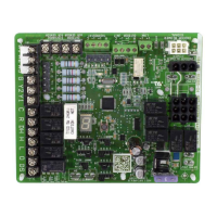
The Lennox Air Handler Control (AHC) is a crucial component for managing the operation of air handler units. It facilitates the control of various functions, including blower speed for both heating and cooling modes, electric heat staging, and dehumidification. The AHC can be configured for either communicating systems, typically using an iComfort® thermostat, or non-communicating systems, which rely on jumper and link settings on the control board itself.
For non-communicating systems, the AHC operates based on the physical jumper and link settings. These settings determine the unit's size code, blower speeds for different modes (cooling, heat, continuous fan), and delay profiles for blower ramping. The control board includes a single-character LED display and a push button for configuration and diagnostic purposes.
In communicating systems, the AHC integrates with iComfort® thermostats, where system configuration is primarily managed through the thermostat's installation instructions. The jumper and link settings on the AHC serve as default settings and only govern system operation if the iComfort® thermostat's configuration settings are unavailable.
The AHC is designed to detect and manage electric heat stages. It can automatically identify the number of field-installed electric heat sections by sensing current through external relay coils. This information is crucial for proper operation, especially in EvenHeat mode.
The AHC offers several features for controlling and monitoring air handler operation:
| Model | 16B27 |
|---|---|
| Type | Heat Pump |
| SEER Rating | Up to 16 |
| HSPF Rating | Up to 9.0 |
| Refrigerant | R-410A |
| Stages | Single-Stage |