
 Need help?
Do you have a question about the Lennox Merit Series 13HPX and is the answer not in the manual?
Verify included items and check for shipping damage upon receipt.
Guidance on slab installation, including proper slope and elevation for water drainage.
Procedure for connecting new refrigerant lines and coils for optimal 13HPX system performance.
Details on the defrost control board, including timing pins and diagnostic indicators.
Cleaning and inspection steps for outdoor unit components and connections.
Filter replacement or cleaning, and checking blower motor seals.
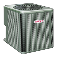
The Lennox Merit® Series 13HPX is an outdoor heat pump unit designed to operate with HFC-410A refrigerant. It must be installed with a matching indoor blower coil and line set as specified in the Lennox Engineering Handbook. These units are specifically designed for use in expansion valve systems and are not compatible with other refrigerant flow control devices. An HFC-410A approved expansion valve must be ordered separately and installed before operating the unit.
The 13HPX unit functions as part of a complete heating and cooling system. It uses HFC-410A refrigerant, which operates at higher pressures than HCFC-22. The outdoor unit and indoor blower cycle on demand from the room thermostat. In cooling mode, the system removes heat from the indoor air and transfers it outdoors. In heating mode, the system reverses this process, extracting heat from the outdoor air and transferring it indoors.
The unit incorporates a defrost system to prevent ice buildup on the outdoor coil during heating operation in cold weather. This system includes a defrost thermostat and a defrost control board. The defrost thermostat, located on the liquid line, senses when the liquid line temperature drops to 42°F (5.5°C) or cooler, initiating the defrost timing. It terminates defrost when the liquid line warms up to 70°F (21°C). The defrost control board manages the defrost cycles, accumulating compressor run times at field-adjustable intervals (30, 60, or 90 minutes). If the defrost thermostat is closed at the end of a selected interval, a defrost cycle begins. The maximum defrost period is 14 minutes.
The unit is equipped with an auto-reset high pressure switch, located on the liquid line, which shuts off the compressor if discharge pressure rises above the factory setting (590 + 10 psig). It also features an auto-reset low pressure switch on the vapor line, which shuts off the compressor if vapor pressure falls below 25 psig and closes at or above 55 psig. This low pressure switch is ignored during defrost operation, the 90-second start-up period, and for 90 seconds when the reversing valve switches modes.
A crankcase heater, if applicable, should be energized 24 hours before unit start-up to prevent compressor damage from slugging. The unit also includes a compressor delay function, which cycles off the compressor for 30 seconds when entering and exiting defrost mode to reduce occasional sounds. A five-minute timed-off delay helps protect the compressor from short-cycling in case of power interruption or pressure switch activation.
For installation, the unit must be positioned to allow adequate clearances for sufficient airflow and servicing, with a minimum clearance of 24 inches (610 mm) between multiple units. Sound-absorbing material like Isomode can be placed under the unit to reduce sound or vibration transmission. The unit should be mounted high enough above ground or roof to allow proper drainage of defrost water and prevent ice buildup, especially in heavy snow areas. It should also be located away from prevailing winter winds and overhanging roof lines.
Refrigerant piping requires careful attention to isolation to prevent vibration and noise transmission. Line sets should be secured with strapping material and wire ties, and any penetrations through walls or floors should use metal sleeves and be sealed with caulk and insulation. Brazing connections must be performed with dry nitrogen flowing through the piping to prevent carbon deposits. Only silver alloy brazing rods rated for HFC-410A refrigerant should be used. Wet cloths should be wrapped around valve bodies during brazing to protect them from heat damage.
Leak testing is crucial after line set connections. An electronic leak detector capable of sensing HFC refrigerant should be used. The system should be pressurized with dry nitrogen and a trace amount of HFC-410A to check for leaks. Evacuation of the system to an absolute pressure of 500 microns (29.9 inches of mercury) within a 20-minute period is essential to remove noncondensables and water vapor, which can corrode copper piping and compressor parts. A thermocouple or thermistor electronic vacuum gauge calibrated in microns (50 to 10,000 microns) is recommended for this process.
Charging the system involves weighing in the refrigerant based on the unit nameplate charge, line set length differences, and indoor unit matchup. Subcooling is the recommended method for checking and adding charge, requiring measurement of outdoor ambient temperature, liquid and vapor line pressures, and liquid line temperature. Airflow should be checked using the Delta-T process in cooling mode or by measuring temperature rise, voltage, and amperage in heating mode.
Routine maintenance is essential for optimal performance. At the beginning of each cooling season, the outdoor unit should be inspected and cleaned, including flushing the outdoor coil with a water hose after ensuring power is off. The outdoor unit fan motor is pre-lubricated and sealed, requiring no further lubrication. All connecting lines, joints, and coils should be visually inspected for oil leaks, and all wiring for loose connections. Voltage supply and amp draw on the outdoor fan motor should be checked. Drain holes in the coil compartment base should be inspected and cleaned.
For the indoor coil, cleaning is necessary, and connecting lines, joints, and the coil should be checked for oil leaks. The condensate line should also be checked and cleaned. Indoor unit maintenance includes cleaning or changing filters. Lennox blower motors are prelubricated and permanently sealed, requiring no additional lubrication.
The unit is equipped with a large-capacity biflow filter drier to keep the system clean and dry. If replacement is needed, a drier of the same design and capacity, suitable for HFC-410A refrigerant, must be used. Diagnostic LEDs on the defrost control board provide visual indications of system status and fault conditions, such as anti-short cycle lockout, low pressure switch fault, and high pressure switch fault, aiding in troubleshooting. The control board also features TEST pins to bypass time delays and initiate defrost cycles for diagnostic purposes.
 General
| Model | 13HPX |
|---|---|
| Type | Heat Pump |
| SEER Rating | Up to 14 |
| HSPF Rating | Up to 8.2 |
| Compressor Type | Scroll |
| Refrigerant | R-410A |
| Stages | Single-stage |
| Warranty | 5-Year Limited Parts |





 To Next Page
