2, Usea servicewrenchwitha hex-headextension
(3/16"forliquid-linevalvesizes;5/16"forvapor-line
valvesizes)to turnthestemclockwiseto seatthe
valve.Tightenitfirmly,
3, Replacethestemcap.Tightenfingertight;thentighten
pertable1(onpage2),
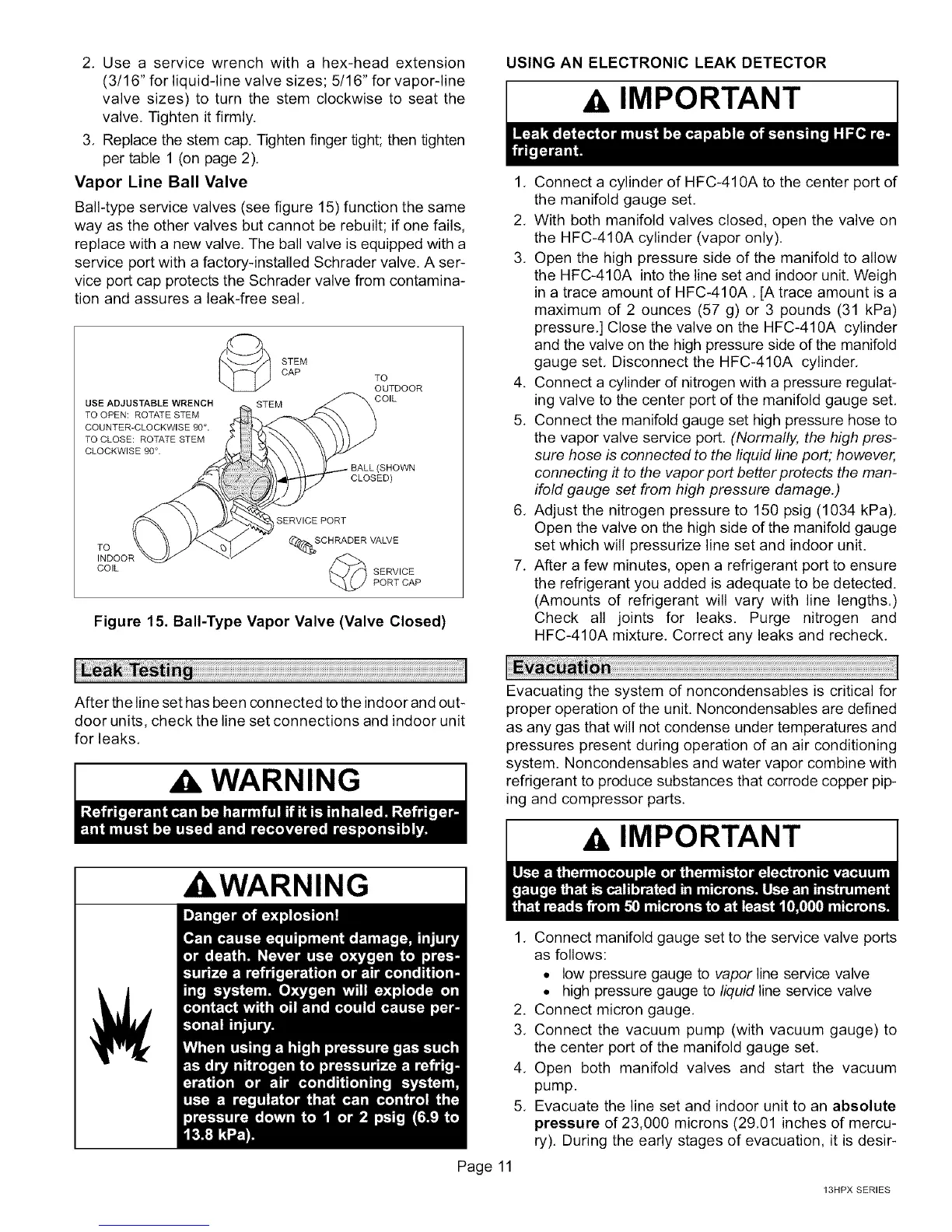
Vapor Line Ball Valve
Ball-typeservicevalves(seefigure15)functionthesame
wayastheothervalvesbutcannotberebuilt;ifonefails,
replacewithanewvalve,Theballvalveisequippedwitha
serviceportwithafactory-installedSchradervalve.Aser-
viceportcapprotectstheSchradervalvefromcontamina-
tionandassuresa leak-freeseal,
STEM
CAP TO
OUTDOOR
USE ADJUSTABLE WRENCH _,,. STEM _(STEM COIL
TO OPEN: ROTATE STEM__.,__
COUNTER-CLOCKWISE 90° .
TO CLOSE: ROTATE STEM
CLOCKWISE 90 °.
(SHOWN
CLOSED)
TO
INDOOR _ _""
COIL SERVICE
PORT CAP
Figure 15. Bali-Type Vapor Valve (Valve Closed)
USING AN ELECTRONIC LEAK DETECTOR
IMPORTANT
1, Connect a cylinder of HFC-410A to the center port of
the manifold gauge set.
2, With both manifold valves closed, open the valve on
the HFC-410A cylinder (vapor only).
3, Open the high pressure side of the manifold to allow
the HFC-410A into the line set and indoor unit. Weigh
in a trace amount of HFC-410A, [A trace amount is a
maximum of 2 ounces (57 g) or 3 pounds (31 kPa)
pressure,] Close the valve on the HFC-410A cylinder
and the valve on the high pressure side of the manifold
gauge set, Disconnect the HFC-410A cylinder,
4. Connect a cylinder d nitrogen with a pressure regulat-
ing valve to the center port of the manifold gauge set,
5. Connect the manifold gauge set high pressure hose to
the vapor valve service port. (Normally, the high pres-
sure hose is connected to the liquid line port; however,
connecting it to the vapor port better protects the man-
ifold gauge set from high pressure damage.)
6, Adjust the nitrogen pressure to 150 psig (1034 kPa),
Open the valve on the high side of the manifold gauge
set which will pressurize line set and indoor unit.
7, After a few minutes, open a refrigerant port to ensure
the refrigerant you added is adequate to be detected.
(Amounts of refrigerant will vary with line lengths.)
Check all joints for leaks. Purge nitrogen and
HFC-410A mixture, Correct any leaks and recheck,
After the line set has been connected tothe indoor and out-
door units, check the line set connections and indoor unit
for leaks.
WARNING
_WARNING
Evacuating the system of noncondensables is critical for
proper operation of the unit. Noncondensables are defined
as any gas that will not condense under temperatures and
pressures present during operation of an air conditioning
system. Noncondensables and water vapor combine with
refrigerant to produce substances that corrode copper pip-
ing and compressor parts.
A IMPORTANT
Page 11
1, Connect manifold gauge set to the service valve ports
as follows:
• low pressure gauge to vapor line service valve
• high pressure gauge to liquid line service valve
2. Connect micron gauge.
3, Connect the vacuum pump (with vacuum gauge) to
the center port of the manifold gauge set,
4, Open both manifold valves and start the vacuum
pump.
5, Evacuate the line set and indoor unit to an absolute
pressure of 23,000 microns (29,01 inches of mercu-
ry). During the early stages of evacuation, it is desir-
13HPX SERIES
 Loading...