INSTALLATION
INSTRUCTIONS
©
2021 Lennox Industries Inc.
Dallas, Texas, USA
THIS MANUAL MUST BE LEFT WITH THE OWNER
FOR FUTURE REFERENCE
WARNING
Improper installation, adjustment, alteration, ser vice or
maintenance can cause property damage, personal
injury or loss of life.
Installation and service must be performed by a li censed
professional HVAC installer (or equivalent) or a service
agency.
WARNING
The clean Air Act of 1990 bans the intentional venting of
refrigerant (CFCs, HCFCs, and HFCs) as of July, 1992.
Approved methods of recovery, recycling or reclaiming
must be followed. Fines and/or incarceration may be
levied for non-compliance.
CAUTION
As with any mechanical equipment, contact with sharp
sheet metal edges can result in personal injury. Take
care while handling this equipment and wear gloves and
protective clothing.
General
Refer to the Product Specications bulletin (EHB) for more
product information.
These instructions are intended as a general guide and
do not supersede local or national codes in any way.
Authorities having jurisdiction should be consulted before
installation.
The MCFA and MCFB Ceiling/Floor indoor units are
matched with an outdoor heat pump unit to create a mini-
split system that uses HFC-410A refrigerant.
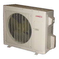
MLB/MPC Outdoor Units
with MCFA/MCFB Indoor
Units
SINGLE-ZONE MINI-SPLIT SYSTEMS
(208/230V) --
Ceiling / Floor Indoor Units
507548-08 10/2021
Supersedes 507548-07
Table of Contents
General .....................................................................................1
Included Parts...........................................................................2
Indoor / Outdoor Unit Match-Ups..............................................2
Model Number Identication .....................................................3
Typical Single-Zone System Components................................4
System Dimensions ..................................................................5
Outdoor Units ................................................................................................... 5
Indoor Units ...................................................................................................... 8
System Clearances ..................................................................8
Outdoor Unit ..................................................................................................... 8
Indoor Unit ........................................................................................................ 9
Torque Requirements for Caps and Fasteners.........................9
Indoor Unit Installation ............................................................10
Unit Placement Considerations ...................................................................... 10
Floor Installation ............................................................................................. 10
Ceiling Installation .......................................................................................... 11
Indoor Unit Condensate Piping Connections ................................................. 11
Outdoor Unit Installation .........................................................12
Placement Considerations ............................................................................. 12
Direct Sunlight, Rain, Snow and Ice Protection .............................................. 12
Prevailing Winds ............................................................................................. 13
Buried Refrigerant Pipe Protection ................................................................. 14
Outdoor Unit Condensate Piping .................................................................... 14
Securing the Outdoor Unit .............................................................................. 14
Refrigerant Piping Connections ..............................................15
Leak Test and Evacuation ......................................................17
Leak Test ........................................................................................................ 17
Triple Evacuation Procedure .......................................................................... 17
Wiring Connections ................................................................17
Outdoor Unit .................................................................................................. 17
Indoor Unit ...................................................................................................... 17
Installation Wiring Requirements .................................................................... 19
Control Board Wiring Connections ................................................................. 20
Unit Start-Up ...........................................................................26
Adding Refrigerant for Longer Line Set ..................................26
Troubleshooting ......................................................................27
Indoor Unit Error Codes ................................................................................. 27
Outdoor Unit Error Codes ............................................................................... 27
Self Clean Feature..................................................................27
Test Run .................................................................................27
Pre-Checks ..................................................................................................... 27
Procedure ....................................................................................................... 27
Dry Mode Operation (Dehumidication) .................................27
Procedure ....................................................................................................... 27
Sequence of Operation .................................................................................. 27