EasyManua.ls Logo

Lennox ML18XC2 Series User Manual

Lennox ML18XC2 Series
23 pages
To Next Page IconTo Next Page
Page #1 background imageLoading...
Page #1 background image
Page 1
WARNING
Improper installation, adjustment, alteration, service
or maintenance can cause property damage, personal
injury or loss of life. Installation and service must be
performed by a licensed professional HVAC installer or
equivalent, service agency, or the gas supplier.
IMPORTANT
The Clean Air Act of 1990 bans the intentional venting of
refrigerant (CFCs, HCFCs and HFCs) as of July 1, 1992.
Approved methods of recovery, recycling or reclaiming
must be followed. Fines and/or incarceration may be
levied for noncompliance.
IMPORTANT
This unit must be matched with an indoor coil as specied
with AHRI. For AHRI Certied system match-ups and
expanded ratings, visit www.LennoxPros.com. Coils
previously charged with HCFC-22 must be ushed.
CAUTION
As with any mechanical equipment, contact with sharp
sheet metal edges can result in personal injury. Take
care while handling this equipment and wear gloves and
protective clothing.
WARNING
Electric Shock Hazard. Can cause injury or
death. Unit must be properly grounded in
accordance with national and local codes.
Line voltage is present at all components
when unit is not in operation on units with
single-pole contactors. Disconnect all remote
electric power supplies before opening
access panel. Unit may have multiple power
supplies.
ML18XC2
Table of Contents
Installation Clearances ...................................................2
Model Number Identication ...........................................2
Dimensions .....................................................................3
Specications .................................................................4
Typical Unit Parts Arrangement ...................................... 5
Operating Gauge Set and Service Valves ......................5
Unit Placement ..............................................................7
Removing and Installing Louvered Panels .....................8
New or Replacement Line Set ........................................9
Brazing Connections ................................................... 11
Flushing Line Set and Indoor Coil ................................14
Installing Indoor Metering Device .................................15
Leak Test Line Set and Indoor Coil ..............................16
Evacuating Line Set and Indoor Coil ...........................17
Electrical .......................................................................18
System Operation .......................................................20
Maintenance ...............................................................20
Servicing Units Void of Charge ...................................22
Start-Up ......................................................................22
Service Literature
UNIT INFORMATION
100051
June 10, 2022
ML18XC2 (HFC-410A) SERIES OUTDOOR UNITS
General Information
These instructions are intended as a general guide and do
not supersede national or local codes in any way. Consult
authorities having jurisdiction before installation.
The Merit
®
ML18XC2 model is designed for use with HFC-
410A refrigerant only. This unit must be installed with an
approved indoor air handler or coil. For AHRI Certied
system match-ups and expanded ratings, visit www.Len-
noxPros.com.
This outdoor unit is designed for use in systems that use
the following refrigerant metering device:
Thermal expansion valve (TXV)
IMPORTANT: Special procedures are required for clean-
ing the all-aluminum coil in this unit. See page 21 in this
instruction for information.
WARNING
To prevent serious injury or death:
1. Lock-out/tag-out before performing maintenance.
2. If system power is required (e.g., smoke detector
maintenance), disable power to blower, remove fan
belt where applicable, and ensure all controllers
and thermostats are set to the “OFF” position before
performing maintenance.
3. Always keep hands, hair, clothing, jewelry, tools, etc.
away from moving parts.
Question and Answer IconNeed help?

Do you have a question about the Lennox ML18XC2 Series and is the answer not in the manual?

Lennox ML18XC2 Series Specifications

General IconGeneral
TypeHeat Pump
SEER RatingUp to 18
RefrigerantR-410A
Stages1
ModelML18XC2
Compressor TypeSingle Stage

Summary

Installation Clearances

Model Number Identification

Dimensions

Specifications

Typical Unit Parts Arrangement

TORQUE REQUIREMENTS

Specifies torque values for fasteners on HVAC components during service or repair.

USING MANIFOLD GAUGE SET

Guidance on selecting and using a manifold gauge set for HFC-410A refrigerant systems.

OPERATING SERVICE VALVES

Explains the function and use of liquid and vapor line service valves for various maintenance tasks.

SERVICE VALVES ANGLE AND BALL

Operating Angle Type Service Valve

Procedure for operating angle type service valves, including back-seating and front-seating.

Operating Ball Type Service Valve

Instructions for operating ball type service valves, including opening and closing procedures.

To Access Service Port

Steps to access and connect a gauge set to the service port, and replace the service port cap.

Reinstall Stem Cap

Procedure for reinstalling the stem cap to protect the valve stem and ensure proper sealing.

Unit Placement

POSITIONING CONSIDERATIONS

Factors to consider for optimal unit positioning, including sound ordinances and proximity to windows.

PLACING UNIT ON SLAB

Guidelines for placing the unit on a slab, ensuring proper drainage and slope tolerance.

ROOF MOUNTING

Instructions for mounting the unit on a roof, including clearance and wind barrier considerations.

Removing and Installing Louvered Panels

New or Replacement Line Set

REFRIGERANT LINE SET

Details on field refrigerant piping, including liquid and suction lines and recommended Lennox line sets.

LINE SET ISOLATION

Importance of isolating refrigerant lines from building structures to prevent vibration and noise transmission.

MATCHING WITH NEW OR EXISTING INDOOR COIL AND LINE SET

Requirements for matching the ML18XC2 with indoor coils, especially those with RFC1 metering lines.

LINE SET INSTALLATION

REFRIGERANT LINE SET - TRANSITION FROM VERTICAL TO HORIZONTAL

Illustrates proper isolation techniques for transitioning refrigerant lines from vertical to horizontal runs.

REFRIGERANT LINE SET - INSTALLING VERTICAL RUNS (NEW CONSTRUCTION SHOWN)

Provides examples of proper refrigerant line set isolation for vertical runs, including insulation guidelines.

REFRIGERANT LINE SET - INSTALLING HORIZONTAL RUNS

Illustrates methods for isolating and securing horizontal refrigerant line sets from floor joists or roof rafters.

Brazing Connections

CUT AND DEBUR

Steps for preparing refrigerant line ends by cutting square and deburring without crimping.

CAP AND CORE REMOVAL

Procedure for removing service caps and cores from suction/vapor and liquid line service ports.

ATTACH THE MANIFOLD GAUGE SET FOR BRAZING LIQUID AND SUCTION / VAPOR LINE SERVICE VALVES

Instructions for connecting a manifold gauge set for brazing, including nitrogen flow setup.

WRAP SERVICE VALVES

Protecting service valve seals and bodies with water-saturated cloths during brazing.

FLOW NITROGEN

Procedure for flowing nitrogen through the system via the service valve stem port.

BRAZE LINE SET

Method for brazing the line set to service valves using water-saturated cloths for cooling.

PREPARATION FOR NEXT STEP

Final steps after brazing, including disconnecting gauges and cooling piping.

Flushing Line Set and Indoor Coil

TYPICAL EXISTING FIXED ORIFICE REMOVAL PROCEDURE (UNCASED OR COIL SHOWN)

Steps for removing a fixed orifice metering device from an uncased indoor coil.

TYPICAL EXISTING EXPANSION VALVE REMOVAL PROCEDURE (UNCASED COIL SHOWN)

Procedure for removing an expansion valve from an uncased indoor coil.

CONNECT GAUGES AND EQUIPMENT FOR FLUSHING PROCEDURE

Connecting gauges and equipment for the system flushing procedure.

FLUSHING LINE SET

Procedure for flushing the line set and indoor unit coil using clean refrigerant.

Installing Indoor Metering Device

INDOOR EXPANSION VALVE INSTALLATION

Detailed steps for installing the indoor expansion valve, including connections and torque.

SENSING BULB INSTALLATION

Instructions for proper orientation and mounting of the sensing bulb for the expansion valve.

EQUALIZER LINE INSTALLATION

Procedure for installing the equalizer line connection to the expansion valve and vapor line.

Leak Test Line Set and Indoor Coil

CONNECT GAUGE SET

Connecting the HFC-410A manifold gauge set for the leak testing procedure.

TEST FOR LEAKS

Procedure for testing the line set and indoor unit for leaks using nitrogen and a leak detector.

Evacuating Line Set and Indoor Coil

CONNECT GAUGE SET

Connecting the gauge set, micron gauge, and vacuum pump for system evacuation.

EVACUATE THE SYSTEM

Steps for evacuating the line set and indoor coil to the required vacuum level.

Electrical

24VAC TRANSFORMER

Information on using the transformer provided with the furnace or air handler for low-voltage control power.

INSTALL THERMOSTAT

Guidelines for installing the thermostat on an indoor wall for optimal performance.

SIZE CIRCUIT AND INSTALL SERVICE DISCONNECT SWITCH

System Operation

UNIT COMPONENTS

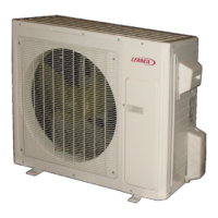
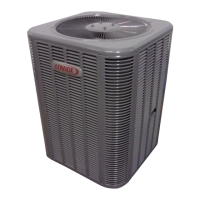
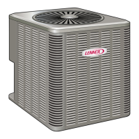
Overview of key components within the outdoor unit and their functions.

Liquid line Filter Drier

Information on the filter drier, its purpose, and replacement requirements for HFC-410A systems.

Low Pressure Switch (S87)

Description of the auto-reset low pressure switch, its location, and operating pressure settings.

High Pressure Switch (S4)

Details on the auto-reset high pressure switch, its location, and trip pressure settings.

Crankcase Heater (HR1) and Thermostat Switch (S40)

Explanation of the crankcase heater and its controlling thermostat switch for compressor protection.

Thermal Protection Switch (S173) – Compressor Mounted

Information on the compressor-mounted thermal protection switch that prevents overheating.

Maintenance

Routine Maintenance

Air Filter

Instructions for locating, checking, cleaning, or replacing the indoor unit's air filter monthly.

Disposable Filter

Guidance on replacing disposable air filters with one of the same type and size.

Reusable Filter

Instructions for cleaning reusable foam filters using mild soap and water solution.

Electronic Air Cleaner

Information on systems equipped with electronic air cleaners and seeking dealer maintenance instructions.

Indoor Unit Condensate Drain

Information on the indoor unit's evaporator coil drain pan for condensate collection and checking drain lines.

Thermostat Operation

Refer to the thermostat homeowner manual for instructions on operating the thermostat.

Preservice Check

Checklist of items to verify before calling for service, including thermostat settings and disconnect switches.

Accessories

Servicing Units Void of Charge

Start-Up

Related product manuals