8. After all of the liquid refrigerant has been recovered,
switch the recovery machine to vapor recovery so that
all of the HCFC-22 vapor is recovered,
NOTE -A single system flush should remove all of the
mineral oil from the existing refrigerant lines and in-
door coil. A second flushing may be done (using clean
refrigerant) if insufficient amounts of mineral oil were
removed during the first flush. Each time the system
is flushed, you must allow the recovery machine
to pull a vacuum on the system at the end of the
procedure.
9. Close the valve on the inverted HCFC-22 drum and
the gauge set valves. Pump the remaining refrigerant
out of the recovery machine and turn the machine off,
10. Use dry nitrogen to break the vacuum on the refriger-
ant lines and indoor coil before removing the recovery
machine, gauges and HCFC-22 refrigerant drum. Re-
install pressure tap valve cores into 13HPX service
valves.
11. Install the provided check/expansion valve (approved
for use with HFC-410A refrigerant) in the liquid line at
the indoor coil.
13HPX units are used in check expansion valve (TXV) sys-
tems only, See the Lennox Engineering Handbook for ap-
proved TXV match-ups and application information.
NOTE - HFC-410A systems will not operate properly with
an HCFC-22 valve.
Check expansion valves equipped with Chatleff fittings are
available from Lennox. Refer to the Engineering Hand-
book for applicable check expansion valves for use with
specific match-ups, See table 3 for applicable check ex-
pansion valve kits,
Table 3. Indoor Check Expansion Valve Kits
Model Kit Number
13HPX-018, -024, -030, -036 49L24
13HPX-042, -048 49L25
13HPX-060 91M02
IMPORTANT
If you install a check expansion valve with an indoor coil
that includes a fixed orifice, remove the orifice before the
check expansion valve is installed. See figure 13 for instal-
lation of the check expansion valve.
/ STRAINER
DISTRIBUTOR _"(_ LITQUBIDLINE
NOTE - If necessary, remove HCFC-22 flow control device (fixed
orifice/thermal expansion valve) from existing line set before instal-
ling HFC-410A approved expansion valve and o-ring,
Figure 13. Metering Device Installation
Manifold gauge sets used with systems charged with
HFC-410A refrigerant must be capable of handling the
higher system operating pressures, The gauges should be
rated for use with pressures of 0 - 800 on the high side and
a low side of 30" vacuum to 250 psi with dampened speed
to 500 psi. Gauge hoses must be rated for use at up to 800
psi of pressure with a 4000 psi burst rating,
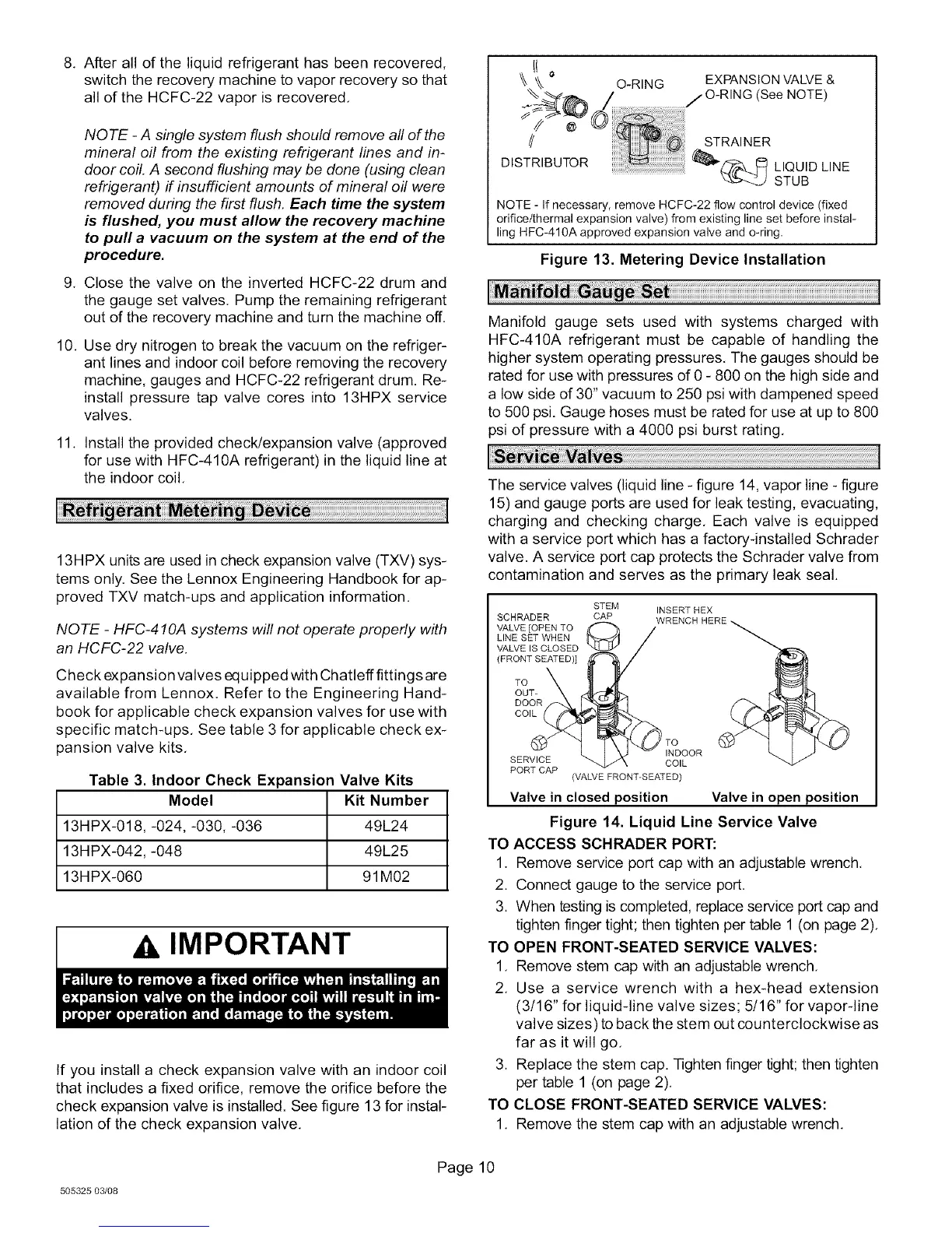
The service valves (liquid line - figure 14, vapor line - figure
15) and gauge ports are used for leak testing, evacuating,
charging and checking charge, Each valve is equipped
with a service port which has a factory-installed Schrader
valve. A service port cap protects the Schrader valve from
contamination and serves as the primary leak seal.
SCHRADER
VALVE [OPEN TO
LINE SET WHEN
VALVE IS CLOSED
]FRONT SEATED)]
TO
OUT-
STEM INSERT HEX
CAP
_TO
INDOOR
SERVICE COIL
PORT CAP
]VALVE FRON%SEATED)
Valve in closed position Valve in open position
Figure 14. Liquid Line Service Valve
TO ACCESS SCHRADER PORT:
1. Remove service port cap with an adjustable wrench,
2. Connect gauge to the service port,
3. When testing is completed, replace service port cap and
tighten finger tight; then tighten per table 1 (on page 2).
TO OPEN FRONT-SEATED SERVICE VALVES:
1, Remove stem cap with an adjustable wrench,
2. Use a service wrench with a hex-head extension
(3/16" for liquid-line valve sizes; 5/16" for vapor-line
valve sizes) to back the stem out counterclockwise as
far as it will go,
3. Replace the stem cap. Tighten finger tight; then tighten
per table 1 (on page 2).
TO CLOSE FRONT-SEATED SERVICE VALVES:
1. Remove the stem cap with an adjustable wrench.
505325 03/08
Page 10
 Loading...