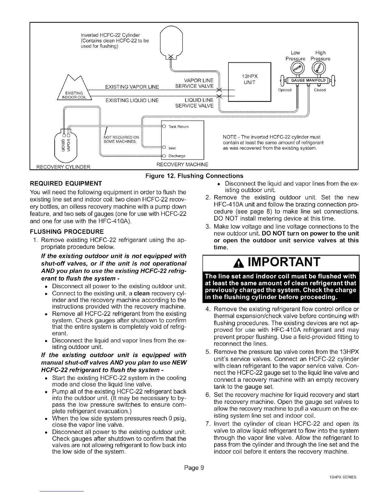
RECOVERY CYLINDER
Inverted HCFC-22 Cylinder
(Contains clean HCFC-22 to be
used for flushing)
EXISTING VAPOR LINE
VAPOR LINE
SERVICE VALVE
EXISTING LIQUID LINE LIQUID LINE
SERVICE VALVE
/ REOU,REDO. ank
SOME MACHINES.
Inlet
r Discharge
RECOVERY MACHINE
Low High
Pressure Pressure
NOTE - The inverted HCFC-22 cylinder must
contain at least the same amount of refrigerant
as was recovered from the existing system.
Figure 12. Flushing Connections
REQUIRED EQUIPMENT
You will need the following equipment in order to flush the
existing line set and indoor coil: two clean HCFC-22 recov-
ery bottles, an oilless recovery machine with a pump down
feature, and two sets of gauges (one for use with HCFC-22
and one for use with the HFC-410A).
FLUSHING PROCEDURE
1. Remove existing HCFC-22 refrigerant using the ap-
propriate procedure below.
If the existing outdoor unit is not equipped with
shut-off valves, or if the unit is not operational
AND you plan to use the existing HCFC-22 refrig-
erant to flush the system -
• Disconnect all power to the existing outdoor unit.
• Connect to the existing unit, a clean recovery cyl-
inder and the recovery machine according to the
instructions provided with the recovery machine.
• Remove all HCFC-22 refrigerant from the existing
system. Check gauges after shutdown to confirm
that the entire system is completely void of refrig-
erant.
• Disconnect the liquid and vapor lines from the ex-
isting outdoor unit.
If the existing outdoor unit is equipped with
manual shut-off valves AND you plan to use NEW
HCFC-22 refrigerant to flush the system -
• Start the existing HCFC-22 system in the cooling
mode and close the liquid line valve.
• Pump all of the existing HCFC-22 refrigerant back
into the outdoor unit. (It may be necessary to by-
pass the low pressure switches to ensure com-
plete refrigerant evacuation.)
• When the low side system pressures reach 0 psig,
close the vapor line valve.
• Disconnect all power to the existing outdoor unit.
Check gauges after shutdown to confirm that the
valves are not allowing refrigerant to flow back into
the low side of the system.
• Disconnect the liquid and vapor lines from the ex-
isting outdoor unit.
2. Remove the existing outdoor unit. Set the new
HFC-410A unit and follow the brazing connection pro-
cedure (see page 8) to make line set connections.
DO NOT install metering device at this time.
3. Make low voltage and line voltage connections to the
new outdoor unit. DO NOT turn on power to the unit
or open the outdoor unit service valves at this
time.
A IMPORTANT
4. Remove the existing refrigerant flow control orifice or
thermal expansion/check valve before continuing with
flushing procedures. The existing devices are not ap-
proved for use with HFC-410A refrigerant and may
prevent proper flushing, Use a field-provided fitting to
reconnect the lines.
5. Remove the pressure tap valve cores from the 13HPX
unit's service valves. Connect an HCFC-22 cylinder
with clean refrigerant to the vapor service valve. Con-
nect the HCFC-22 gauge set to the liquid line valve and
connect a recovery machine with an empty recovery
tank to the gauge set,
6. Set the recovery machine for liquid recovery and start
the recovery machine. Open the gauge set valves to
allow the recovery machine to pull a vacuum on the ex-
isting system line set and indoor coil.
7. Invert the cylinder of clean HCFC-22 and open its
valve to allow liquid refrigerant to flow into the system
through the vapor line valve. Allow the refrigerant to
pass from the cylinder and through the line set and the
indoor coil before it enters the recovery machine.
Page 9
13HPX SERIES
 Loading...