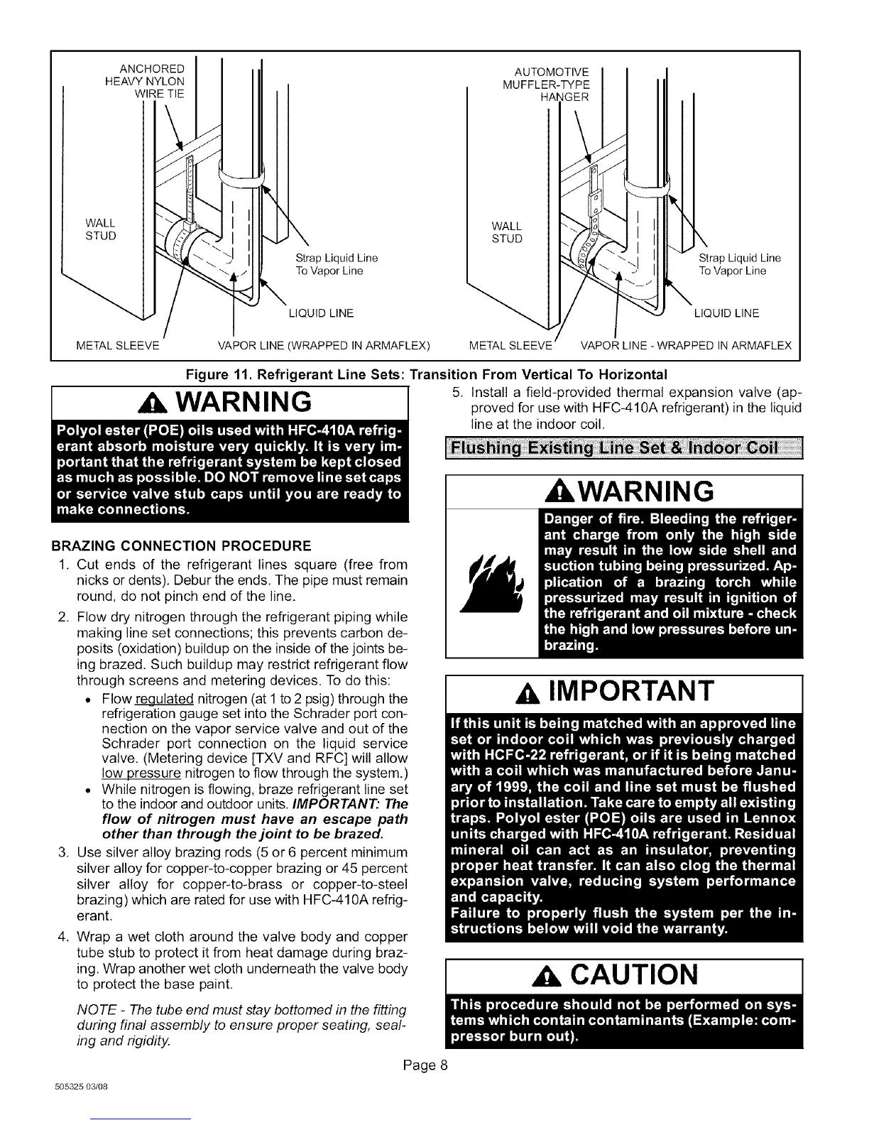
ANCHORED
HEAVY NYLON
WIRE TIE
AUTOMOTIVE
MUFFLER-TYPE
HANGER
WALL
STUD
WALL
STUD
Strap Liquid Line
To Vapor Line
LIQUID LINE
Strap Liquid Line
To Vapor Line
LIQUID LINE
METAL SLEEVE
VAPOR LINE (WRAPPED IN ARMAFLEX)
VAPOR LINE -WRAPPED IN ARMAFLEX
Figure 11. Refrigerant Line Sets: Transition From Vertical To Horizontal
WARNING I 5, Install a field-provided thermal expansion valve (ap-proved for use with HFC-410A refrigerant) in the liquid
line at the indoor coil,
BRAZING CONNECTION PROCEDURE
1, Cut ends of the refrigerant lines square (free from
nicks or dents), Debur the ends. The pipe must remain
round, do not pinch end of the line.
2, Flow dry nitrogen through the refrigerant piping while
making line set connections; this prevents carbon de-
posits (oxidation) buildup on the inside of the joints be-
ing brazed. Such buildup may restrict refrigerant flow
through screens and metering devices. To do this:
• Flow_ulated nitrogen (at 1 to 2 psig) through the
refrigeration gauge set into the Schrader port con-
nection on the vapor service valve and out of the
Schrader port connection on the liquid service
valve. (Metering device [TXV and RFC] will allow
low pressure nitrogen to flow through the system.)
• While nitrogen is flowing, braze refrigerant line set
to the indoor and outdoor units, IMPORTANT." The
flow of nitrogen must have an escape path
other than through the joint to be brazed.
3, Use silver alloy brazing rods (5 or 6 percent minimum
silver alloy for copper-to-copper brazing or 45 percent
silver alloy for copper-to-brass or copper-to-steel
brazing) which are rated for use with HFC-410A refrig-
erant,
4. Wrap a wet cloth around the valve body and copper
tube stub to protect it from heat damage during braz-
ing, Wrap another wet cloth underneath the valve body
to protect the base paint,
NOTE - The tube end must stay bottomed in the fitting
during final assembly to ensure proper seating, seal-
ing and rigidity.
Page 8
505325 03/08
_WARNING
IMPORTANT
CAUTION
 Loading...