WARNING
CAUTION
Outdoor units operate under a wide range of weather con-
ditions; therefore, several factors must be considered
when positioning the outdoor unit. Unit must be positioned
to give adequate clearances for sufficient airflow and servi-
cing. A minimum clearance of 24 inches (610 mm) be-
tween multiple units must be maintained. Refer to figure 1
for installation clearances.
1. Place a sound-absorbing material, such as Isomode,
under the unit if it will be installed in a location or posi-
tion that will transmit sound or vibration to the living
area or adjacent buildings.
2. Mount unit high enough above ground or roof to allow
adequate drainage of defrost water and prevent ice
build-up.
3. In heavy snow areas, do not locate unit where drifting
will occur. The unit base should be elevated above the
depth of average snows.
NOTE- Elevation of the unit may be accomplished by
constructing a frame using suitable materials. Ira sup-
port frame is constructed, it must not block drain holes
in unit base.
4. When installed in areas where low ambient tempera-
tures exist, locate unit so winter prevailing winds do
not blow directly into outdoor coil.
5. Locate unit away from overhanging roof lines which
would allow water or ice to drop on, or in front of, coil
or into unit.
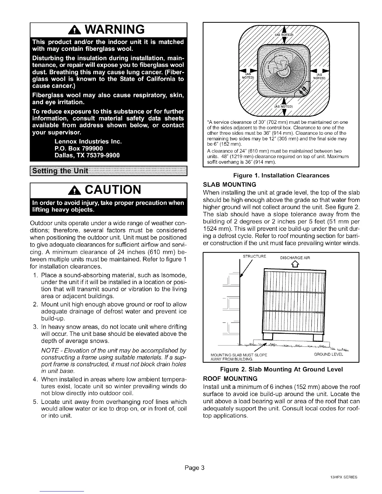
(AS NOTED)
*A service clearance of 30" (702 mm) must be maintained on one
of the sides adjacent to the control box. Clearance to one of the
other three sides must be 36" (914 mm), Clearance to one of the
remaining two sides may be 12" (305 mm) and the final side may
be 6" (152 mm).
A clearance of 24" (610 mm) must be maintained between two
units, 48" (1219 mm) clearance required on top of unit, Maximum
soffit overhang is 36" (914 mm).
Figure 1 Installation Clearances
SLAB MOUNTING
When installing the unit at grade level, the top of the slab
should be high enough above the grade so that water from
higher ground will not collect around the unit, See figure 2.
The slab should have a slope tolerance away from the
building of 2 degrees or 2 inches per 5 feet (51 mm per
1524 mm). This will prevent ice build-up under the unit dur-
ing a defrost cycle. Refer to roof mounting section for barri-
er construction if the unit must face prevailing winter winds,
STRUCTURE DISCHARGE AIR
,
I/I/I/I/I/
l/I/////
MOUNTING SLAB MUST SLOPE
AWAY FROM BUILDING.
GROUNDLEVEL
Figure 2. Slab Mounting At Ground Level
ROOF MOUNTING
Install unit a minimum of 6 inches (152 mm) above the roof
surface to avoid ice build-up around the unit. Locate the
unit above a load bearing wall or area of the roof that can
adequately support the unit, Consult local codes for roof-
top applications,
Page 3
13HPX SERIES
 Loading...