PREVAILINGWINTERWINDS
©
I WINDBARRIER I
INLET AIR
INLET AIR INLET AIR
0 0
0
INLET AIR
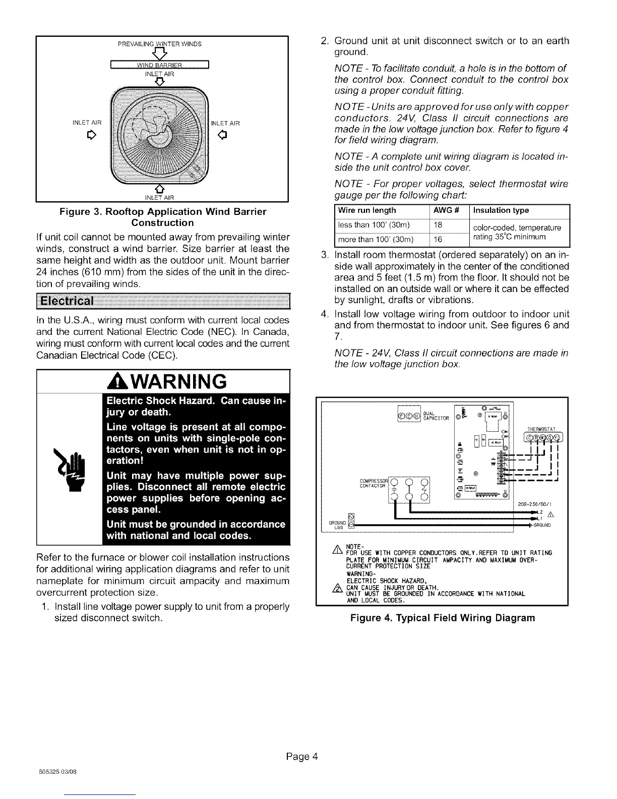
Figure 3. Rooftop Application Wind Barrier
Construction
If unit coil cannot be mounted away from prevailing winter
winds, construct a wind barrier. Size barrier at least the
same height and width as the outdoor unit. Mount barrier
24 inches (610 mm) from the sides of the unit in the direc-
tion of prevailing winds.
In the U.S.A., wiring must conform with current local codes
and the current National Electric Code (NEC). In Canada,
wiring must conform with current local codes and the current
Canadian Electrical Code (CEC).
WARNING
I
Refer to the furnace or blower coil installation instructions
for additional wiring application diagrams and refer to unit
nameplate for minimum circuit ampacity and maximum
overcurrent protection size.
1. Install line voltage power supply to unit from a properly
sized disconnect switch.
.
.
.
Ground unit at unit disconnect switch or to an earth
ground.
NOTE - To facilitate conduit, a hole is in the bottom of
the control box. Connect conduit to the control box
using a proper conduit fitting.
NO TE - Units are approved for use only with copper
conductors. 24V, Class II circuit connections are
made in the low voltage junction box. Refer to figure 4
for field wiring diagram.
NOTE - A complete unit wiring diagram is located in-
side the unit control box cover.
NOTE - For proper voltages, select thermostat wire
gauge per the following chart:
Wire run length AWG # Insulation type
less than 100' (30m) 18 color-coded, temperature
more than 100' (30m) 16 rating 35°C minimum
Install room thermostat (ordered separately) on an in-
side wall approximately in the center of the conditioned
area and 5 feet (1.5 m) from the floor. It should not be
installed on an outside wall or where it can be effected
by sunlight, drafts or vibrations.
Install low voltage wiring from outdoor to indoor unit
and from thermostat to indoor unit. See figures 6 and
7.
NOTE - 24V, Class II circuit connections are made in
the low voltage junction box.
OUAL
CAPACITOR
@_ @ ._.-
_C_
--- @
THERIIOST AT
,_ II_j, I
_-_J_j II
..... .I
208-230/60/I
mll 2 _
1,6ROUND
Z_ NOTE-
FOR USE WITH COPPER CONDUCTORS ONLY.REFER TO UNIT RATING
PLATE FOR MINIMUM CIRCUIT AUPACITY AND MAXIMUM OVER-
CURRENT PROTECTION SIZE
WARNING-
ELECTRIC SHOCK HAZARD,
Z_ CAN CAUSE INJURYOR DEATH.
UNIT MUST BE GROUNDED IN ACCORDANCE WITH NATIONAL
AND LOCAL CODES.
Figure 4. Typical Field Wiring Diagram
505325 03/08
Page 4
 Loading...