Table 12. HFC-410A Temp. (°F) - Pressure (Psig)
°F Psig °F Psig °F Psig °F Psig
-40 10.1 21 80.5 56 158.2 91 278.2
-35 13.5 22 82.3 57 161 92 282.3
-30 17.2 23 84.1 58 163.9 93 286.5
-25 21.4 24 85.9 59 166.7 94 290.8
-20 25.9 25 87.8 60 169.6 95 295.1
-18 27.8 26 89.7 61 172.6 96 299.4
-16 29.7 27 91.6 62 175.4 97 303.8
-14 31.8 28 93.5 63 178.5 98 308.2
-12 33.9 29 95.5 64 181.6 99 312.7
-10 36.1 30 97.5 65 184.3 100 317.2
-8 38.4 31 99.5 66 187.7 101 321.8
-6 40.7 32 100.8 67 190.9 102 326.4
-4 43.1 33 102.9 68 194.1 103 331
-2 45.6 34 105 69 197.3 104 335.7
0 48.2 35 107.1 70 200.6 105 340.5
1 49.5 36 109.2 71 203.9 106 345.3
2 50.9 37 111.4 72 207.2 107 350.1
3 52.2 38 113.6 73 210.6 108 355
4 53.6 39 115.8 74 214 109 360
5 55 40 118 75 217.4 110 365
6 56.4 41 120.3 76 220.9 111 370
7 57.9 42 122.6 77 224.4 112 375.1
8 59.3 43 125 78 228 113 380.2
9 60.8 44 127.3 79 231.6 114 385.4
10 62.3 45 129.7 80 235.3 115 390.7
11 63.9 46 132.2 81 239 116 396
12 65.4 47 134.6 82 242.7 117 401.3
13 67 48 137.1 83 246.5 118 406.7
14 68.6 49 139.6 84 250.3 119 412.2
15 70.2 50 142.2 85 254.1 120 417.7
16 71.9 51 144.8 86 258 121 423.2
17 73.5 52 147.4 87 262 122 428.8
18 75.2 53 150.1 88 266 123 434.5
19 77 54 152.8 89 270 124 440.2
20 78.7 55 155.5 90 274.1 125 445.9
The outdoor unit and indoor blower cycle on demand from
the room thermostat. If the thermostat blower switch is in
the ON position, the indoor blower operates continuously.
FILTER DRIER
The unit is equipped with a large-capacity biflow filter drier
which keeps the system clean and dry. If replacement is
necessary, order another of the same design and capacity.
The replacement filter drier must be suitable for use with
HFC-410A refrigerant.
LOW PRESSURE SWITCH
The 13HPX is equipped with an auto-reset low pressure
switch which is located on the vapor line. The switch shuts
off the compressor when the vapor pressure falls below the
factory setting. This switch, which is ignored during defrost
operation, closes at pressures at or above 55 psig and
opens at 25 psig. It is not adjustable.
HIGH PRESSURE SWITCH
The 13HPX is equipped with an auto-reset high pressure
switch (single-pole, single-throw) which is located on the
liquid line, The switch shuts off the compressor when dis-
charge pressure rises above the factory setting. The
switch is normally closed and is permanently adjusted to
trip (open) at 590 _+10 psig (4412 _+69 kPa),
NOTE - A Schrader core is under the pressure switches.
The 13HPX defrost system includes two components: a
defrost thermostat and a defrost control.
DEFROST THERMOSTAT
The defrost thermostat is located on the liquid line between
the check/expansion valve and the distributor. When de-
frost thermostat senses 42°F (5.5°C) or cooler, the ther-
mostat contacts close and send a signal to the defrost con-
trol board to start the defrost timing. It also terminates
defrost when the liquid line warms up to 70°F (21°C).
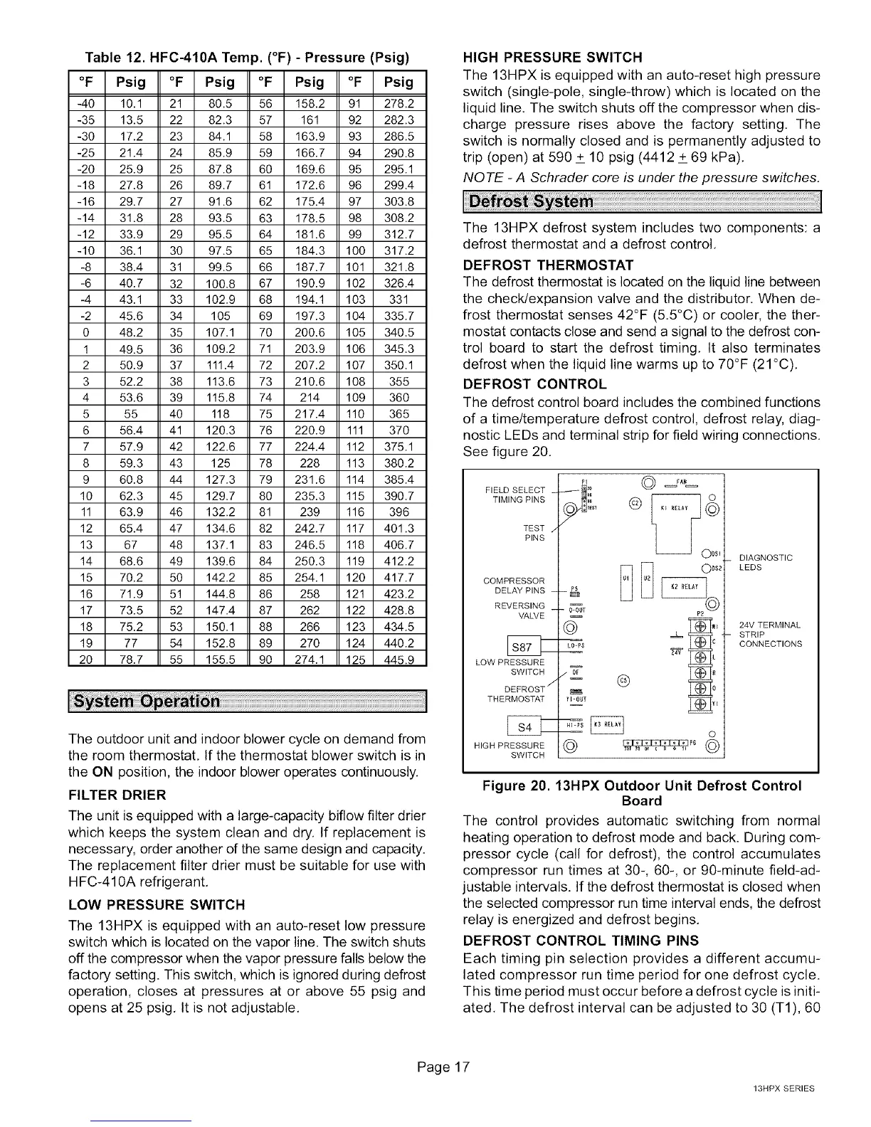
DEFROST CONTROL
The defrost control board includes the combined functions
of a time/temperature defrost control, defrost relay, diag-
nostic LEDs and terminal strip for field wiring connections.
See figure 20.
FIELD SELECT
TIMING PINS
TEST
PINS
COMPRESSOR
DELAY PINS
REVERSING
VALVE
LOW PRESSURE
SWITCH
DEFROST _"
THERMOSTAT
HIGH PRESSURE
SWITCH
ODSl
ODS2
0-0UT P2
Bt_€
YFOUT
o
DIAGNOSTIC
LEDS
24V TERMINAL
STRIP
CONNECTIONS
Figure 20.13HPX Outdoor Unit Defrost Control
Board
The control provides automatic switching from normal
heating operation to defrost mode and back. During com-
pressor cycle (call for defrost), the control accumulates
compressor run times at 30-, 60-, or 90-minute field-ad-
justable intervals. If the defrost thermostat is closed when
the selected compressor run time interval ends, the defrost
relay is energized and defrost begins.
DEFROST CONTROL TIMING PINS
Each timing pin selection provides a different accumu-
lated compressor run time period for one defrost cycle.
This time period must occur before a defrost cycle is initi-
ated, The defrost interval can be adjusted to 30 (T1), 60
Page 17
13HPX SERIES
 Loading...