11
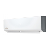
Air Outlet
Air Inlet
6 in
152 mm
Figure 26. Securing Outdoor Unit to Brackets
Refrigerant Piping Connections
Field piping consists of two copper lines connecting the
outdoor unit to the indoor unit. The connections are made
using the provided brass are nuts at the end of the
refrigerant piping connections.
1. Choose the correct pipe sizes for your application
using “Table 4. Refrigerant Piping and Indoor Unit
Connection Sizes”.
2. Conrm that you are using the correct diameter piping.
3. Determine the necessary piping length required for
the application.
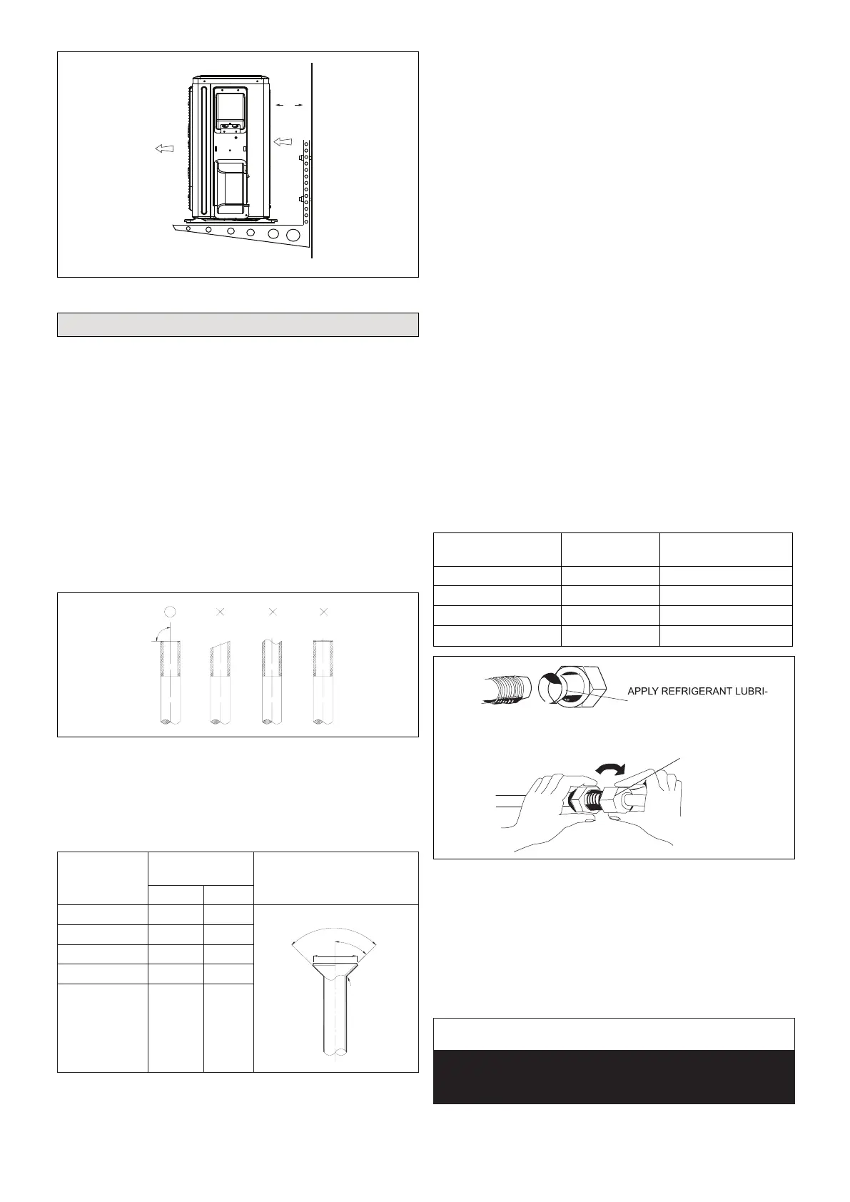
4. Cut the selected pipes with a pipe cutter. Make the
cuts at and smooth as illustrated in “Figure 27.
Cutting Piping”.
Figure 27. Cutting Piping
5. Insulate the copper piping.
6. Insert a are nut onto each pipe before aring.
7. Use “Table 3. Flaring Pipe” to properly are the pipe.
Table 3. Flaring Pipe
Pipe Diameter
Flare Dimension
A (mm)
Flare Shape
Min Max
1/4” 8.3 8.7
3/8” 12.0 12.4
1/2” 15.4 15.8
5/8” 18.6 19.1
3/4” (22.9) 22.9 23.3
8. After aring the pipe, temporarily sealed pipe ends
with adhesive tape to avoid contaminants from
entering the pipes.
9. The seal on the unit refrigerant piping connections
should remain in place until the last possible moment.
This will prevent dust or water from getting into the
refrigerant piping before it is connected.
10. CAREFULLY adjust refrigerant piping connections to
suit the application.
11. Slowly loosen one of the are nuts to release the
factory nitrogen charge from the indoor units only.
12. Remove the are nuts from the connections on the
unit and discard the seal from each of the piping
connections.
13. Slide the are nuts onto the ends of the eld-provided
refrigerant piping before using a suitable aring tool to
are the end of the copper pipe.
14. Apply recommended HFC-410A refrigerant lubricant
to the outside of the ared refrigerant lines.
15. Align the threaded connections with the
ared refrigerant lines. Tighten the are nuts
lightly at rst to obtain a smooth match as
illustrated in “Figure 28. Making Connections
(Male to Female Connection)”.
Table 4. Refrigerant Piping and Indoor Unit
Connection Sizes
Size
(Btuh)
Liquid Line
in.
Suction Line
in.
9K 1/4 3/8
12K 1/4 1/2
18K 1/4 1/2
24K
3/8 5/8
A
B
CANT ON THE OUTSIDE OF
THE FLARE
MALE FLARE
CONNECTION
Figure 28. Making Connections
(Male to Female Connection)
16. Once snug, continue another half-turn on each nut
which should create a leak-free joint. A torque wrench
may be used to tighten are nuts using “Table 5. Flare
Nut Torque Recommendations”.
17. After refrigerant piping has been installed and checked
for leaks, apply insulation over all ared connections.
IMPORTANT
Always use two wrenches when tightening are nuts to
avoid twisting refrigerant piping. DO NOT over-tighten
are nuts.
 Loading...