14
Terminal block
Terminal Block
Cover
Screw
Cable Clamp
The wiring diagram is located
on the inside of the indoor unit’s
terminal block cover.
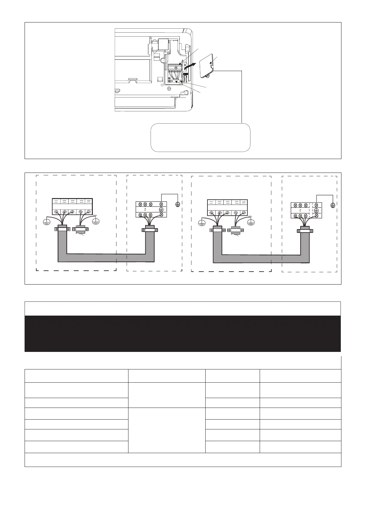
Figure 31. Indoor Unit Terminal Block
208/230V Outdoor Unit
Terminal Block
From Power
Supply
Terminal Block
208/230V Indoor Unit
Outdoor Unit Indoor Unit
3
2
L1
L2
1
Y/G
1
3
Y/G
Y/G
115VAC Outdoor Unit
Terminal Block
From Power
Supply
Terminal Block
115VAC Indoor Unit
Outdoor Unit Indoor Unit
3
2
L
N
1
Y/G
1
3
Y/G
Y/G
*
*
18 and 24K
unit has
five terminal
sets.
Figure 32. Single Zone Wiring
IMPORTANT
This unit must be properly grounded and protected by a circuit breaker. The ground wire for the unit must not be
connected to a gas or water pipe, a lightning conductor or a telephone ground wire.
Do not connect power wires to the outdoor unit until all other wiring and piping connections have been completed.
Do not install the unit near a lighting appliance that includes a ballast. The ballast may affect remote control operation.
Table 8. Single Zone Installation Electrical
Outdoor Unit Model Voltage/Phase, Hz MCA Max Fuse
MHB009S4S-1L
115 / 1 / 60
20 30
MHB012S4S-1L 18.5 25
MHB009S4S-1P
208-230 / 1 / 60
12 15
MHB012S4S-1P 15 15
MHB018S4S-1P 15 20
MHB024S4S-1P 19 30
MCA = Minimum Circuit Amps
 Loading...