Page 28
ADDING OR REMOVING REFRIGERANT
This system uses HFC-410A refrigerant which operates at much higher pressures than HCFC-22. The pre-installed liquid
line lter drier is approved for use with HFC-410A only. Do not replace it with components designed for use with HCFC-22.
This unit is NOT approved for use with coils which use capillary tubes or xed orices as a refrigerant metering device.
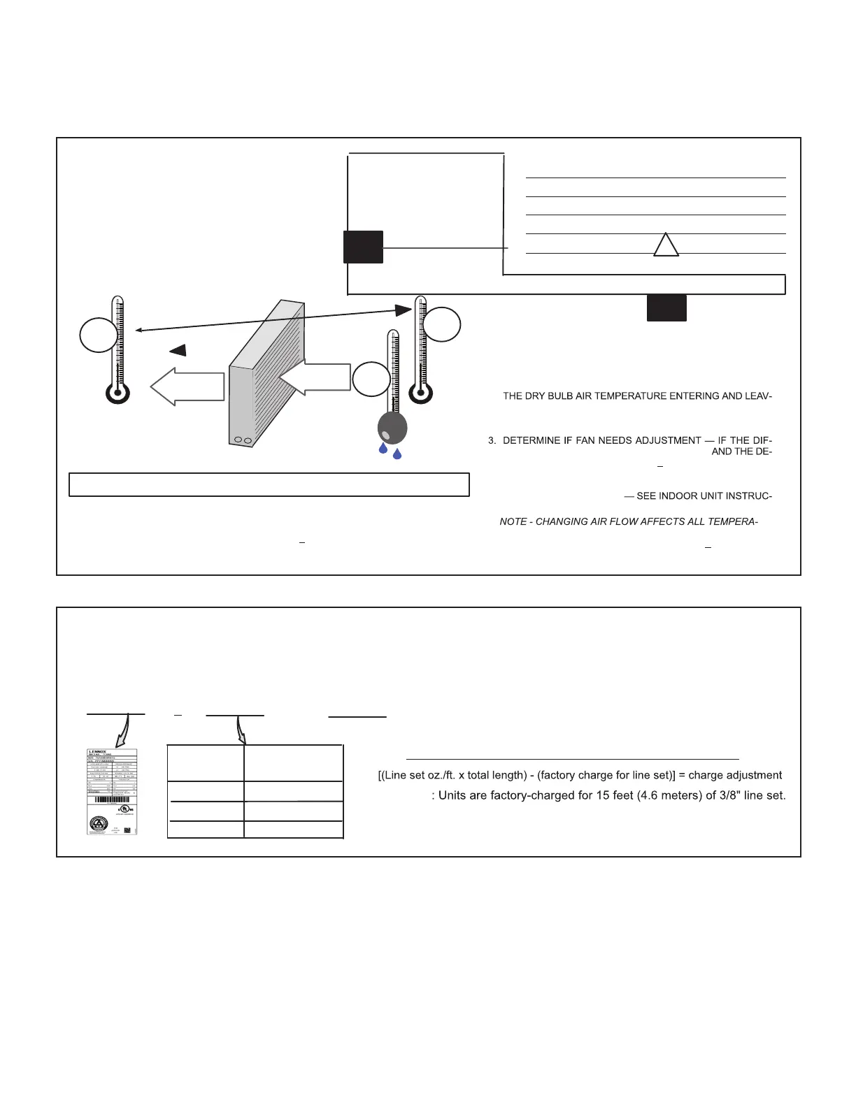
Check airow using the Delta-T (DT) process using the illustration in gure 19.
Cº T
DROP
– DT = ºF ACTION
53º 19 –15 = 4 INCREASE THE AIRFLOW
58º 14 –15 = -1 (WITHIN +3º RANGE) NO CHANGE
62º 10 –15 = -5 DECREASE THE AIRFLOW
DT
80 24 24 24 23 23 22 22 22 20 19 18 17 16 15
78 23 23 23 22 22 21 21 20 19 18 17 16 15 14
76 22 22 22 21 21 20 19 19 18 17 16 15 14 13
74 21 21 21 20 19 19 18 17 16 16 15 14 13 12
72 20 20 19 18 17 17 16 15 15 14 13 12 11 10
70 19 19 18 18 17 17 16 15 15 14 13 12 11 10
57 58 59 60 61 62 63 64 65 66 67 68 69 70
TEMPERATURE OF AIR
ENTERING INDOOR COIL ºF
INDOOR
COIL
DRY BULB
DRY
BULB
WET
BULB
B
T
DROP
19º
A
DRY-BULB
WET-BULB ºF
A
72º
B
64º
C
53º
AIR
FLOW
AIR
FLOW
ALL TEMPERATURES ARE
EXPRESSED IN ºF
1. DETERMINE THE DESIRED DT — MEASURE ENTERING AIR
TEMPERATURE USING DRY BULB (A) AND WET BULB (B).
DT IS THE INTERSECTING VALUE OF A AND B IN THE
TABLE (SEE TRIANGLE).
2. FIND TEMPERATURE DROP ACROSS COIL
— MEASURE
ING THE COIL (A AND C). TEMPERATURE DROP FORMULA:
(T
DROP
) = A MINUS C.
FERENCE BETWEEN THE MEASURED T
DROP
SIRED DT (T
DROP
–DT) IS WITHIN +3º, NO ADJUSTMENT IS
NEEDED. SEE EXAMPLE AT LEFT:
4. ADJUST THE FAN SPEED
TIONS TO INCREASE/DECREASE FAN SPEED.
ASSUME DT = 15 AND A TEMP. = 72º, BELOW C TEMPERATURES REQUIRE ACTION:
AIRFLOW
INDOOR COIL
TURES; RECHECK TEMPERATURES TO CONFIRM THAT THE
TEMPERATURE DROP AND DT ARE WITHIN +
3º.
FIGURE 19. Checking Indoor Airow over Evaporator Coil using Delta-T Chart
WEIGH-IN
Liquid Line
Set Diameter
HFC-410A
(ounces per foot)
5/16”
3/8”
1/2”
0.40
0.60
1.00
NOTE - The nameplate is shown for illustration purposes only. Go to
actual nameplate on outdoor unit for charge information.
CHARGING METHOD
NOTE - Insulate liquid line when it is routed through areas where
the surrounding ambient temperature could become higher than
the temperature of the liquid line or when pressure drop is equal
to or greater than 20 psig.
mount specified
on nameplate
Adjust amount for variation in
line set length and liquid line
diameter using table below.
Total charge
+
=
64ºF (17.7ºC) and Below
Example
Factory charge for 3/8" is 0.60 oz/ft x 15 = 9.0 ounces.
Charging Formula for Liquid Line Charge Adjustments
FIGURE 20. Using HFC-410A Weigh-In Method
 Loading...