Page 12
8. Gas Valve (Figure 6)
The ML180DF uses internally redundant gas valve to as
sure safety shut-off. If the gas valve must be replaced, the
same type valve must be used.
24VAC terminals and valve switch are located on the valve. All
terminals on the gas valve are connected to wires from the in
tegrated control. 24V applied to the terminals energizes the
valve.
Inlet and outlet pressure taps are located on the valve. A regu
lator adjustment screw is located on the valve.
LPG changeover kits are available from Lennox. Kits include
burner orifices and a gas valve regulator spring.
9. Combustion Air Inducer (B6)
All ML180DF units use a combustion air inducer to move air
through the burners and heat exchanger during heating op
eration. The blower uses a 120VAC motor. The motor oper
ates during all heating operation and is controlled by inte
grated control A92. The inducer also operates for 15 sec
onds before burner ignition (pre‐purge) and for 5 seconds
after the gas valve closes (post‐purge).
A pressure switch mounted on the combustion air inducer ori
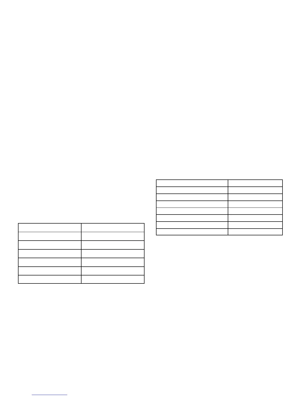
fice plate is used to prove inducer operation. The combustion
air inducer orifice will be different for each model. See table 5
for orifice sizes. The switch monitors air pressure in the induc
er housing. During normal operation, the pressure in the
housing is negative. If pressure becomes less negative (sig
nifying any obstruction in the flue) the pressure switch opens.
When the proving switch opens, the integrated control (A92)
immediately de-energizes the gas valve to prevent burner
operation.
TABLE 5
ML180DF Unit
C.A.I. Orifice Size
045P24A 1.094
045P36A 1.063
070(X)P36A 1.344
090P36B 1.531
090(X)P48B 1.531
110(X)P60C 1.718
10. Combustion Air Inducer
Pressure Switch (S18)
ML180DF series units are equipped with a combustion air
pressure switch located on the combustion air inducer ori
fice bracket. The switch is connected to the combustion air
inducer housing by means of a flexible silicone hose. It mon
itors negative air pressure in the combustion air inducer
housing.
The switch is a SPST Normally open proving switch electri
cally connected to the furnace control. The purpose of the
switch is to prevent burner operation if the combustion air in
ducer is not operating or if the flue becomes obstructed.
On start‐up, the switch senses that the combustion air in
ducer is operating. It closes a circuit to the integrated con
trol when pressure inside the combustion air inducer de
creases to a certain set point. Set points vary depending on
unit size. See table 6. The pressure sensed by the switch is
negative relative to atmospheric pressure. If the flue be
comes obstructed during operation, the switch senses a
loss of negative pressure (pressure becomes more equal
with atmospheric pressure) and opens the circuit to the in
tegrated control and gas valve. A bleed port on the switch
allows relatively dry air in the vestibule to purge switch tub
ing, to prevent condensate build up.
TABLE 6
ML180DF Set Point inches w.c.
045P24A 0.60
045P36A 0.60
070(X)P36A 0.65
090P36B 0.60
090(X)P48B 0.60
110(X)P60C 0.65
110P60C 0.69
The switch is factory set and is not field adjustable. It is a
safety shut‐down control in the furnace and must not be by-
passed for any reason. If switch is closed or by-passed, the
integrated control will not initiate ignition at start up.
Troubleshooting
See figure 9 for measuring operating pressure and check
ing resistance in the pressure switch.
 Loading...