Page 13
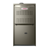
FIGURE 9
MULTI−METER
SET TO MEASURE OHMS
To
Pressure Switch
High
Low
or
Remove tubing from CAI and
insert “Tee” and additional tubing.
Field Provided
Tubing To CAI Port
11. Blower Motors and Capacitors
All ML180DF units use direct drive blower motors. All motors
are 120V permanent split capacitor motors to ensure maxi
mum efficiency. See Specifications section at the front of this
manual for motor specifications. Ratings for capacitors will
be on motor nameplate.
12. Secondary Limit Control
The secondary limit is located in the blower compartment on
the back side of the blower housing. See figure 10. When ex
cess heat is sensed in the blower compartment, the limit will
open. If the limit is open, the furnace control energizes the sup
ply air blower and closes the gas valve. The limit automatically
resets when unit temperature returns to normal. The secon
dary limit cannot be adjusted.
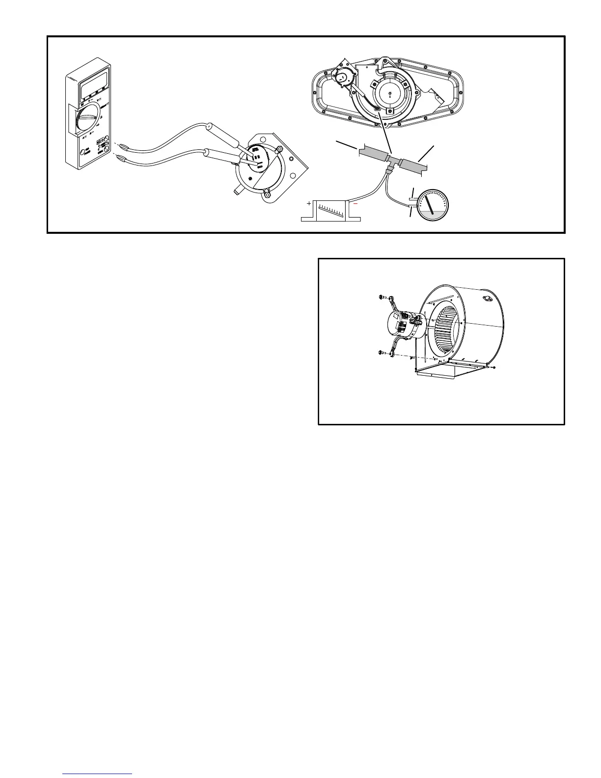
FIGURE 10
To Remove Blower From Unit:
1. Disconnect Power, 2. Remove internal flue pipe and chase
3. Remove Control Box 4. Remove Bolts. 5. Unplug Motor
Wires From Control Board. Then Slide Out Front of Unit.
Supply Air Blower
 Loading...