Page 12
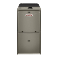
Primary Limit Location and Heat Exchanger
Install limit face down
FIGURE 7
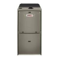
4. Gas Valve (FIGURE 8)
-
-
GAS VALVE SHOWN IN ON POSITION
MANIFOLD
PRESSURE
OUTLET
PORT
INLET
PORT
ADJUSTMENT SCREW
(under barbed fitting)
FIGURE 8
5. Flame Sensor (FIGURE 6)
-
NOTE - The ML193UHE is polarity sensitive. Make sure
that the furnace is wired correctly and is properly ground-
ed.
To Measure Flame Signal - Integrated Control:
-
1 -
2 -
3 -
6. Ignitor (FIGURE 6)
-
-
 Loading...