Page 37
Accessory Terminals
One line voltage “EAC” 1/4” spade terminal is provided
on the furnace integrated control. See FIGURE 60 for in-
tegrated control conguration. This terminal is energized
when the indoor blower is operating. Any accessory rated
up to one amp can be connected to this terminal with the
neutral leg of the circuit being connected to one of the pro-
vided neutral terminals. If an accessory rated at greater
than one amp is connected to this terminal, it is necessary
to use an external relay.
One line voltage 120V “HUM” 1/4” spade terminal is pro-
vided on the furnace integrated control. See FIGURE 60
for integrated control conguration. This terminal is ener-
gized in the heating mode when the combustion air induc-
er is operating. Any humidier rated up to one amp can be
connected to this terminal with the neutral leg of the circuit
being connected to one of the provided neutral terminals.
If a humidier rated at greater than one amp is connected
to this terminal, it is necessary to use an external relay
relay
One 24V ”HUM” 1/4” spade terminal is provided on the
furnace integrated control. See FIGURE 60 for integrat-
ed control conguration. The terminal is energized in the
heating mode when the combustion air inducer is operat-
ing and the pressure switch is closed. Any humidier rated
up to 0.5 amp can be connected to this terminal with the
ground leg of the circuit connected to ground or the ”C”
terminal.
Thermostat
Install the room thermostat according to the instructions
provided with the thermostat. See FIGURE 59 for thermo-
stat designations. If the furnace is being matched with a
heat pump, refer to the thermostat installation instruction
for set up.
Indoor Blower Speeds
1 - When the thermostat is set to “FAN ON,” the indoor
blower will run continuously on the (FAN) speed when
there is no cooling or heating demand. See table below
for for allowable circulation speeds.
2 - When the ML193UHE is running in the heating mode,
the indoor blower will run on the heating speed (HEAT).
See table below for allowable heating speeds.
3 - When there is a cooling demand, the indoor blower will
run on the cooling speed (COOL).
Generator Use - Voltage Requirements
The following requirements must be kept in mind when
specifying a generator for use with this equipment:
• The furnace requires 120 volts + 10% (Range: 108
volts to 132 volts)
• The furnace operates at 60 Hz + 5% (Range: 57
Hz to 63 Hz)
• The furnace integrated control requires both po-
larity and proper ground. Both polarity and proper
grounding should be checked before attempting to
operate the furnace on either permanent or tempo-
rary power
• Generator should have a wave form distortion of
less than 5% THD (total harmonic distortion).
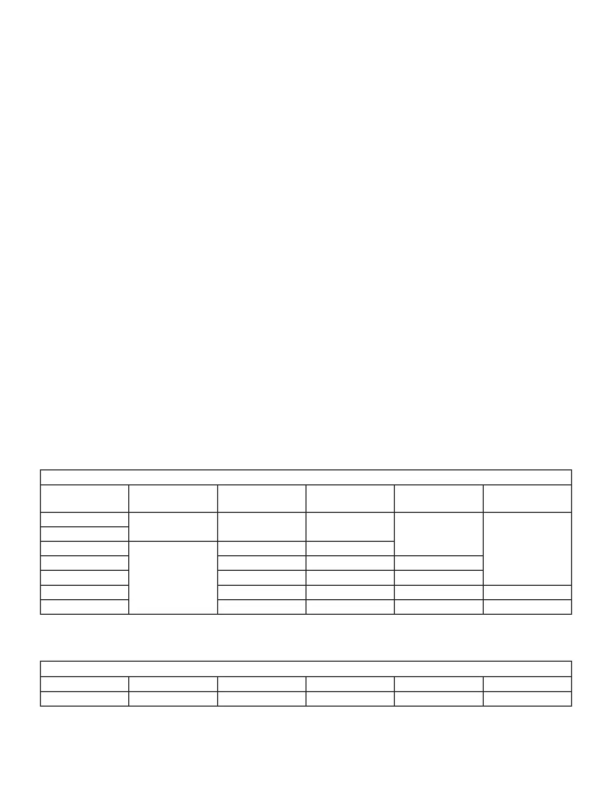
Allowable Heating Speeds
ML193UHE
Model Number
Red Yellow Blue Brown Black
-030
Allowed
Factory Setting
Allowed
Allowed
Not Allowed
-045
-070
Not Allowed
Allowed Factory Setting
-09036C Not Allowed Allowed Factory Setting
-09048C Allowed Factory Setting Allowed
-11048C Not Allowed Allowed Factory Setting Allowed
-11060C Allowed Factory Setting Allowed Not Allowed
Allowable Circulation Speeds
Model Number Red Yellow Blue Brown Black
All Models Factory Setting Not Allowed Not Allowed Not Allowed Not Allowed
 Loading...