Page 1
© 2019 Lennox Industries Inc.
Litho U.S.A.
Corp. 1905
ML193UHE
Service Literature
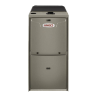
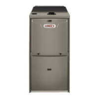
ML193UHE SERIES UNITS
ML193UHE series units are high-efficiency gas fur
naces manufactured with Lennox DuralokPlust alumi
nized steel clamshell-type heat exchangers, with a stainless
steel condensing coil. ML193UHE units are available in
heating input capacities of 30,000 to 110,000 Btuh (8.8 to
32.2 kW) and cooling applications from 2 through 5 tons (7.0
through 17.6 kW). Refer to Engineering Handbook for proper
sizing.
Units are factory equipped for use with natural gas. A kit is
available for conversion to LPG operation. All ML193UHE
units are equipped with a hot surface ignition system. The
gas valve is redundant to assure safety shut-off as re
quired by C.S.A.
The heat exchanger, burners and manifold assembly can be
removed for inspection and service. The maintenance section
gives a detailed description on how this is done.
The ML193UHE can be “twinned” with a second unit. See
twinning kit 16W72 for information for two units to operate
as one, in a shared duct system controlled by a single ther
mostat.
All specifications are subject to change. Procedures outlined
in this manual are presented as a recommendation only
and do not supersede or replace local or state codes.
WARNING
Electric shock hazard. Can cause injury
or death. Before attempting to perform
any service or maintenance, turn the
electrical power to unit OFF at discon
nect switch(es). Unit may have multiple
power supplies.
Table of Contents
Specifications 2.................................
Optional Accessories 4..........................
Blower Performance Data 5......................
I-Unit Components 7............................
II Placement and Installation 20....................
III-Start-Up 39...................................
IV-Heating System Service Checks 40..............
V-Typical Operating Conditions 44.................
VI-Maintenance 45...............................
VII-Sequence of Operation and Flow Charts 48......
WARNING
Improper installation, adjustment, alteration, service
or maintenance can cause property damage, person
al injury or loss of life. Installation and service must
be performed by a licensed professional HVAC in
staller (or equivalent), service agency or the gas sup
plier.
CAUTION
As with any mechanical equipment, contact with
sharp sheet metal edges can result in personal in
jury. Take care while handling this equipment and
wear gloves and protective clothing.