Page 30
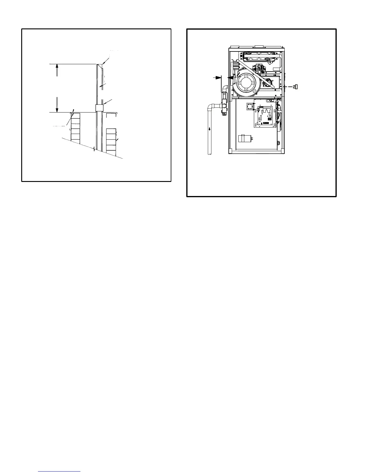
NOTE − Do not discharge exhaust gases directly into any chimney or vent stack. If ver-
tical discharge through an existing unused chimney or stack is required, insert piping
inside chimney until the pipe open end is above top of chimney and terminate as illus-
trated. In any exterior portion of chimney, the exhaust vent must be insulated.
FIGURE 43
STRAIGHT−CUT OR
ANGLE−CUT IN DIRECTION
OF ROOF SLOPE
EXHAUST VENT
1/2" (13mm)
WEATHERPROOF
INSULATION
SHOULDER OF FITTINGS
PROVIDE SUPPORT
OF PIPE ON TOP PLATE
EXTERIOR
PORTION OF
CHIMNEY
INSULATE
TO FORM
SEAL
SHEET
METAL TOP
PLATE
SIZE TERMINATION
PIPE PER TABLE 6.
ML195UH NON−DIRECT VENT APPLICATION
USING EXISTING CHIMNEY
Minimum 12" (305MM)
above chimney top
plate or average snow
accumulation
Condensate Piping
This unit is designed for either right- or left-side exit of con-
densate piping in upflow applications. In horizontal applica-
tions, the condensate trap must extend below the unit. An
8" service clearance is required for the condensate trap.
Refer to figures 44 and 45 for condensate trap locations.
Figure 51 shows trap assembly using 1/2" PVC or 3/4"
PVC.
NOTE − If necessary the condensate trap may be installed
up to 5´ away from the furnace. Use PVC pipe to connect
trap to furnace condensate outlet. Piping from furnace
must slope down a minimum of 1/4" per ft. toward trap.
1 − Determine which side condensate piping will exit the
unit, location of trap, field−provided fittings and length of
PVC pipe required to reach available drain.
2 − Use a 3/8 allen wrench and remove plug (figure 44)
from the cold end header box at the appropriate loca-
tion on the side of the unit. Install field−provided 1/2
NPT male fitting into cold end header box. Use Teflon
tape or appropriate pipe dope.
3 − Install the cap over the clean out opening at the base of
the trap. Secure with clamp. See figure 51.
FIGURE 44
CONDENSATE TRAP AND PLUG LOCATIONS
(Unit shown in upflow position)
NOTE − In upflow applications where side return
air filter is installed on same side as the conden-
sate trap, filter rack must be installed beyond
condensate trap or trap must be re−located to
avoid interference.
Trap
(same on
right side)
Plug
(same on left side)
1−1/2 in.
4 − Install drain trap using appropriate PVC fittings, glue
all joints. Glue the provided drain trap as shown in fig-
ure 51. Route the condensate line to an open drain.
Condensate line must maintain a 1/4" downward slope
from the furnace to the drain.
5 − Figures 46 and 47 show the furnace and evaporator
coil using a separate drain. If necessary the conden-
sate line from the furnace and evaporator coil can
drain together. See figures 48, 49 and 50.
Upflow furnace (figure 46) − In upflow furnace applica-
tions the field provided vent must be a minimum 1" to a
maximum 2" length above the condensate drain outlet
connection. Any length above 2" may result in a
flooded heat exchanger if the combined primary drain
line were to become restricted.
Horizontal furnace (figure 50) − In horizontal furnace
applications the field provided vent must be a mini-
mum 4" to a maximum 5" length above the condensate
drain outlet connection. Any length above 5" may re-
sult in a flooded heat exchanger if the combined pri-
mary drain line were to become restricted.
6 − If unit will be started immediately upon completion of
installation, prime trap per procedure outlined in Unit
Start−Up section.
 Loading...