EasyManua.ls Logo

Lennox ML196DF045XE36B

Lennox ML196DF045XE36B
52 pages
To Next Page IconTo Next Page
Loading...
Page 1
© 2021 Lennox Industries Inc.
Litho U.S.A.
Corp. 1910-L7
02/2021
ML196DFE
Service Literature
ML196DFE SERIES UNITS
ML196DFE series units are high-efficiency gas fur
naces manufactured with Lennox DuralokPlust alumi
nized steel clamshell-type heat exchangers, with a stainless
steel condensing coil. ML196DFE units are available in
heating input capacities of 44,000 to 110,000 Btuh and
cooling applications from 2 through 5 tons. Refer to Product
Specifications for proper sizing.
Units are factory equipped for use with natural gas. A kit is
available for conversion to LP/Propane operation. All
ML196DFE units are equipped with a hot surface ignition
system. The gas valve is redundant to assure safety
shut-off as required by C.S.A.
The heat exchanger, burners and manifold assembly can be
removed for inspection and service. The maintenance section
gives a detailed description on how this is done.
All specifications are subject to change. Procedures outlined
in this manual are presented as a recommendation only
and do not supersede or replace local or state codes.
WARNING
Electric shock hazard. Can cause injury
or death. Before attempting to perform
any service or maintenance, turn the
electrical power to unit OFF at discon
nect switch(es). Unit may have multiple
power supplies.
Table of Contents
Specifications 2.................................
Optional Accessories 3..........................
Blower Performance Data 4......................
I-Unit Components 5............................
II Placement and Installation 19....................
III-Start-Up 39...................................
IV-Heating System Service Checks 40..............
V-Typical Operating Conditions 44.................
VI-Maintenance 45...............................
VII-Wiring and Sequence of Operation 48...........
VIII-Troubleshooting 49...........................
WARNING
Improper installation, adjustment, alteration, service
or maintenance can cause property damage, person
al injury or loss of life. Installation and service must
be performed by a licensed professional HVAC in
staller (or equivalent), service agency or the gas sup
plier.
CAUTION
As with any mechanical equipment, contact with
sharp sheet metal edges can result in personal in
jury. Take care while handling this equipment and
wear gloves and protective clothing.
Question and Answer IconNeed help?

Do you have a question about the Lennox ML196DF045XE36B and is the answer not in the manual?

Lennox ML196DF045XE36B Specifications

General IconGeneral
BrandLennox
ModelML196DF045XE36B
CategoryFurnace
Efficiency96% AFUE
Heating Capacity45, 000 BTU
Blower MotorVariable Speed
Fuel TypeNatural Gas
StagesSingle Stage
TypeGas

Summary

UNIT INFORMATION

ML196 DFE SERIES UNITS

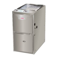
Overview of the ML196DFE series gas furnace units, detailing their features and capabilities.

SPECIFICATIONS

Model Specifications and Performance Data

Covers heating, blower, electrical, and shipping details across various ML196DFE models.

OPTIONAL ACCESSORIES

Accessory Categories and Components

Lists cabinet, drain, controls, and filter kits available as optional accessories.

BLOWER DATA

Blower Performance by Model

Detailed performance data (air volume/watts) for each ML196DFE model.

PARTS ARRANGEMENT

FIGURE 1 Component Layout

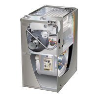
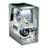
Illustrates the unit's main components and their physical layout.

I-UNIT COMPONENTS

ELECTROSTATIC DISCHARGE (ESD) Precautions

Safety guidelines for handling electronic components to prevent damage.

Control Box Components Overview

Details internal components within the unit's control box, including transformer and ignition control.

INTEGRATED CONTROL System Operation

Heating Components Overview

Flame Rollout Switches

Safety switches that detect abnormal flame conditions and shut down the unit.

Heat Exchanger Assembly

Details the primary and secondary heat exchanger assembly used for heat transfer.

Primary Limit Control

Over-temperature safety control located in the heat exchanger vestibule.

Gas Valve and Flame Sensor Details

Ignitor Component Description

Describes the mini-nitride ignitor made from proprietary ceramic material.

Combustion Air Inducer and Pressure Switch

Blower Compartment Components

Blower Wheel Replacement Procedure

Instructions for replacing the blower wheel, emphasizing proper centering.

Secondary Limit Control Function

Details the secondary limit control's role in preventing overheating.

Motor Module Replacement

Motor Testing Procedures

Procedures for testing the motor and control module before replacement.

Motor Module Installation Steps

Steps for installing a new motor control module, including torque specifications.

II-PLACEMENT AND INSTALLATION

Pipe & Fittings Specifications

Lists approved materials and standards for vent and drain piping.

Joint Cementing Procedure for Piping

Venting Practices and Guidelines

Vent Piping Guidelines and Sizing Process

Typical Vent Pipe Terminations

Intake Piping Installation

General Guidelines for Vent Terminations

Non-Direct Vent Termination Clearances

Direct Vent Termination Clearances

Direct Vent IntakeExhaust Piping Details

Direct Vent Application Using Existing Chimney

Field Fabricated & Alternate Wall Terminations

Non-Direct Vent Exhaust Piping Details

Condensate Piping Installation

Procedures for installing and routing the condensate drain line, including trap location.

Condensate Drain Components and Setup

Evaporator Coil Condensate Drain Connections

Condensate Trap Assembly Guide

III-START-UP

Pre-Operation Checks and Heating Start-Up

Covers initial checks, safety procedures, and starting the furnace in heating mode.

Gas Valve Operation and Failure Modes

Explains gas valve function and troubleshooting startup issues.

IV-HEATING SYSTEM SERVICE CHECKS

Gas Piping and Pressure Testing

Covers gas piping installation, leak testing, and pressure checks.

Supply and Manifold Pressure Verification

Procedures for checking manifold and supply line pressures for proper operation.

Gas Flow and Combustion Checks

High Altitude Operation Considerations

Information on operating the furnace at different altitudes and required adjustments.

Grounding and Voltage Checks

V-TYPICAL OPERATING CHARACTERISTICS

Blower Operation, Temperature Rise, and Static Pressure

Details blower function, temperature rise measurement, and static pressure adjustment.

Blower Speed Tap Adjustments

Instructions for changing blower speeds using the integrated control taps.

VI-MAINTENANCE

Routine Maintenance: Blower, Filters, Electrical

Covers cleaning blowers, inspecting filters, and checking electrical connections.

Seasonal Care: Winterizing and Condensate Trap

Steps for unit winterization and maintenance of the condensate trap.

Heat Exchanger Cleaning Procedure

Burner Assembly Cleaning Procedure

VII-WIRING DIAGRAM AND SEQUENCE OF OPERATION

VIII-Troubleshooting: Heating Sequence of Operation

Troubleshooting: Cooling Sequence of Operation

Guide for diagnosing cooling system issues based on operational sequence and error codes.

Troubleshooting: Fan and Accessory Operation

Guide for diagnosing issues related to fan and accessory operation.

Related product manuals