Do you have a question about the Lennox ML195UH 045XP24B and is the answer not in the manual?
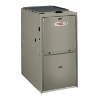
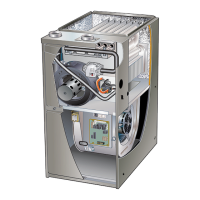
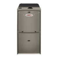
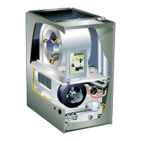
Overview of the ML195UH series high-efficiency gas furnaces.
Critical safety warnings regarding electric shock, installation, and sharp edges.
Detailed specifications including performance, connections, blower, electrical, and shipping data.
Lists and categorizes optional accessories like cabinet, drain, filter, and termination kits.
Air volume and wattage data for various blower speeds and static pressures.
Continued air volume and wattage data for different blower speeds and static pressures.
Details on the transformer, door interlock switch, and integrated ignition control.
Safety warnings for electrical shock and electrostatic discharge when handling components.
Table detailing LED flash codes for troubleshooting furnace operation.
Terminal designations, diagnostic codes, and wiring information for the ignition control.
Information on adjusting heating and cooling fan off delay settings for comfort.
Details on flame rollout switches, limit control, burners, heat exchanger, and gas valve.
Procedures for checking ignitor resistance and voltage, including test steps.
Table listing combustion air inducer orifice sizes for different unit models.
Table specifying pressure switch set points based on altitude.
Description and identification of the blower motor and capacitor.
Guidelines for providing adequate air for combustion and ventilation.
Cautions regarding corrosive atmospheres and air supply for safe operation.
Defines unconfined and confined space requirements for furnace installation.
Important notes on using PVC/CPVC/ABS pipe, primer, and solvent cement.
Cautions regarding exhaust discharge into stacks and positive pressure vent pipes.
Steps for sizing vent pipe and table for minimum vent pipe lengths.
Diagrams for upflow and horizontal non-direct vent intake pipe connections.
Caution regarding sizing inlet air openings when combustion air is from an exhaust-serviced space.
Diagram illustrating pipe insulation placement in unconditioned spaces.
Diagram showing clearances for non-direct vent terminations in USA and Canada.
Diagram showing clearances for direct vent terminations in USA and Canada.
Table for size reduction and diagrams for direct vent exhaust terminations.
Diagrams and guidelines for field-fabricated wall terminations.
Diagrams for non-direct vent exhaust piping terminations.
Diagrams for separate drain connections with evaporator coils.
Diagram illustrating separate drain connection for horizontal evaporator coils.
Diagrams for common drain connections with evaporator coils (upflow/horizontal).
Note regarding venting A/C condensate drain outlet for furnace pressure switch operation.
Diagrams and instructions for assembling 3/4" PVC condensate trap and drain.
Diagrams and instructions for assembling 1/2" PVC condensate trap and drain.
Covers preliminary checks, heating start-up, gas valve operation, and failure to operate.
Critical warning about potential fire or explosion if instructions are not followed exactly.
Information on gas piping, flexible connectors, and leak testing procedures.
Procedures for testing gas supply and manifold pressures for proper operation.
Steps to check voltage between Line Neutral and 'C' terminal, and Line Hot and Neutral.
General blower operation dependent on thermostat and temperature rise requirements.
Critical safety warning before performing any maintenance on the furnace.
Instructions for inspecting, cleaning, or replacing furnace air filters.
Wiring diagram for control 100973 and associated component charts.
Flow chart detailing normal and abnormal heating sequences based on control logic.
Flow chart detailing normal and abnormal cooling sequences based on control logic.
Charts related to blower speeds and jackplug connections for control 103085.
Flow chart detailing normal and abnormal heating sequences for control 103085.
| Brand | Lennox |
|---|---|
| Model | ML195UH 045XP24B |
| Category | Furnace |
| Type | Gas |
| Efficiency | 95% AFUE |
| Stages | Single-Stage |
| Ignition System | Hot Surface Ignition |
| Input BTU | 44, 000 BTU/h |
| Output BTU | 42, 000 BTU/h |
| Vent Type | Direct Vent |
| Warranty | 5-Year Limited Warranty on covered components |