Page 36
1 - Determine which side condensate piping will exit the
unit, location of trap, field-provided fittings and length of
PVC pipe required to reach available drain.
2 - For furnaces with a 1/2” drain connection use a 3/8 al
len wrench and remove plug (figure 43) from the cold
end header box at the appropriate location on the side
of the unit. Install field-provided 1/2 NPT male fitting
into cold end header box. For furnaces with a 3/4”
drain connection use a large flat head screw driver or a
1/2” drive socket extension and remove plug. Install
provided 3/4 NPT street elbow fitting into cold end
header box. Use Teflon tape or appropriate pipe dope.
3 - Install the cap over the clean out opening at the base
of the trap. Secure with clamp. See figure 49.
4 - Install drain trap using appropriate PVC fittings, glue
all joints. Glue the provided drain trap as shown in fig
ure 49. Route the condensate line to an open drain.
5 - Figure 47 shows the furnace and evaporator coil using
a separate drain. If necessary, the condensate line
from the furnace and evaporator coil can drain togeth
er. See figures 48 and 46. The field provided vent must
be a minimum 1” to a maximum 2” length above the
condensate drain outlet connection.
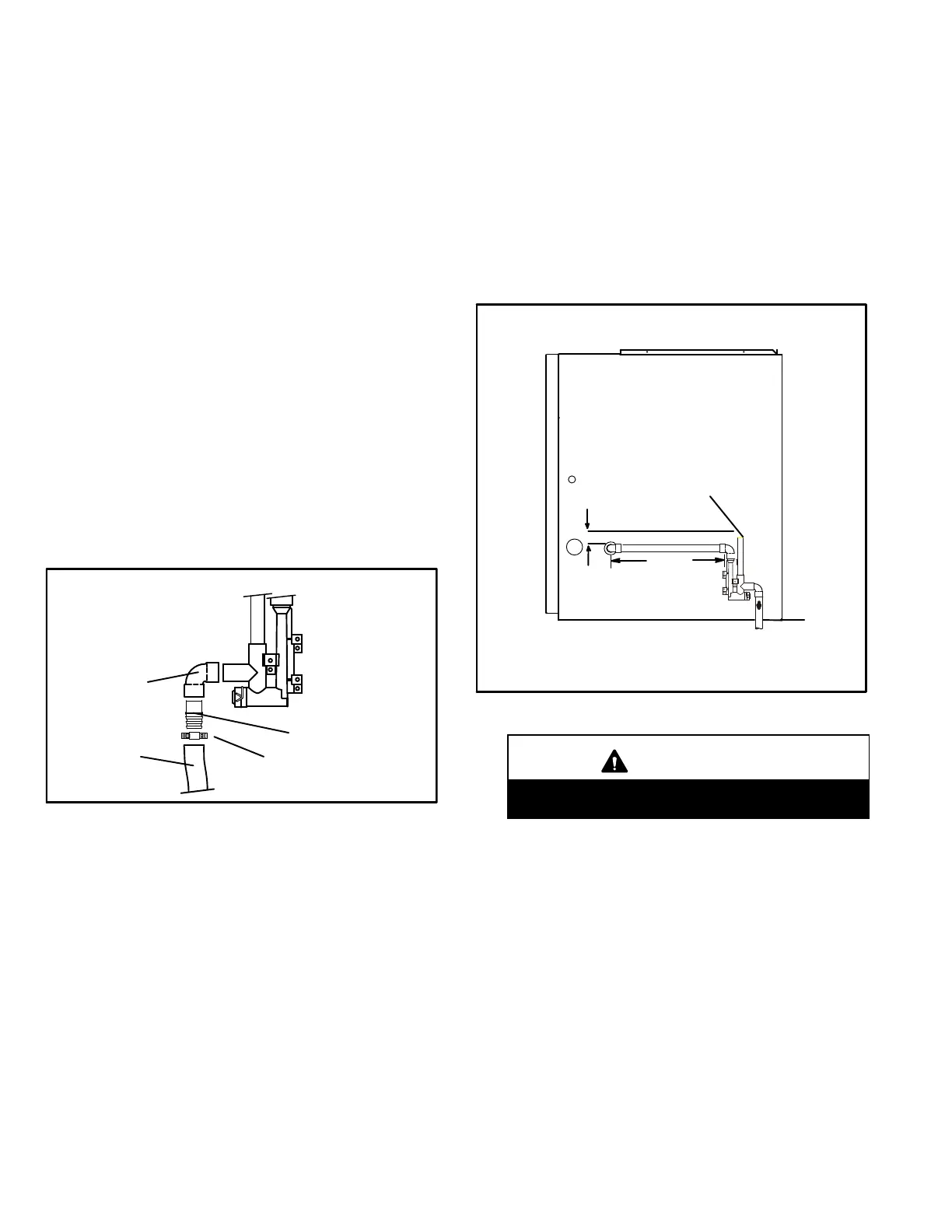
NOTE - Appropriately sized tubing and barbed fitting may
be used for condensate drain. Attach to the drain on the
trap using a hose clamp. See figure 44.
FIGURE 44
Tubing
Hose Clamp
Barbed Fitting
Field Provided Drain Components
Elbow
6 - If unit will be started immediately upon completion of
installation, prime trap per procedure outlined in Unit
Start-Up section.
Condensate line must slope downward away from the
trap to drain. If drain level is above condensate trap,
condensate pump must be used. Condensate drain
line should be routed within the conditioned space to
avoid freezing of condensate and blockage of drain
line. If this is not possible, a heat cable kit may be used
on the condensate trap and line. Heat cable kit is avail
able from Lennox in various lengths; 6 ft. (1.8m) - kit
no. 26K68 and 24 ft. (7.3m) - kit no. 26K69.
FIGURE 45
CONDENSATE TRAP LOCATION
(shown with right side exit of condensation)
5’ max.
to drain
1” min.
2” max.
Trap can be installed a maximum
of 5ft. from furnace (*PVC only)
Field Provided Vent
1” min. 2” max. above
condensate drain.
*Piping from furnace must slope down a
minimum 1/4” per ft. toward trap
CAUTION
Do not use copper tubing or existing copper
condensate lines for drain line.
 Loading...