EasyManua.ls Logo

Lennox ML196UHE Series

Lennox ML196UHE Series
57 pages
To Next Page IconTo Next Page
Loading...
Page 1
UNIT INFORMATIONUNIT INFORMATION
Service Literature
©2016 Lennox Industries, Inc.
WARNING
Improper installation, adjustment, alteration, service
or maintenance can cause property damage,
personal injury or loss of life. Installation and service
must be performed by a licensed professional HVAC
instale (or equivalent), service agency or the gas
supplier.
CAUTION
As with any mechanical equipment, contact with
sharp sheet metal edges can result in personal
injury. Take care while handling this equipment and
wear gloves and protective clothing.
󰀩
  
      

        



      


󰀨



-


WARNING
Electric shock hazard. Can cause injury
or death. Before attempting to perform
any service or maintenance, turn the
electrical power to unit OFF at disconnect
switch(es). Unit may have multiple power
supplies.
Table of Contents










ML196UHE


ML196UHE SERIES UNITS
Question and Answer IconNeed help?

Do you have a question about the Lennox ML196UHE Series and is the answer not in the manual?

Lennox ML196UHE Series Specifications

General IconGeneral
ModelML196UHE Series
Efficiency RatingUp to 96% AFUE
Blower TypeVariable Speed
Fuel TypeNatural Gas
WarrantyLimited Lifetime Heat Exchanger Warranty
Heating Capacity (BTU/h)60, 000 - 100, 000

Summary

ML196 UHE Series Units

General Safety Warnings

Electrical shock and improper installation warnings.

Handling Precautions

Caution regarding sharp metal edges and protective gear.

Specifications

Gas Heating Performance

Details AFUE, input/output Btuh, and temperature rise.

Energy Star Certification

Indicates Energy Star certification status.

Connections and Blower Data

Covers pipe sizes, blower specs, and electrical data.

Shipping Data

Provides shipping weight information.

Optional Accessories

Cabinet and Condensate Drain Kits

Lists optional cabinet and condensate drain accessories.

Controls and Filter Kits

Details optional control and filter kit options.

Night Service and Termination Kits

Lists optional night service and termination kits.

Venting Accessories

Lists optional venting accessories.

Blower Performance Data

ML196 UH030 XE36 B Performance

Blower data for model 030XE36B.

ML196 UH045 XE36 B Performance

Blower data for model 045XE36B.

ML196 UH070 XE36 B Performance

Blower data for model 070XE36B.

ML196 UH070 XE48 B Performance

Blower data for model 070XE48B.

Blower Performance Data

ML196 UH090 XE36 C Performance

Blower data for model 090XE36C.

ML196 UH090 XE48 C Performance

Blower data for model 090XE48C.

ML196 UH090 XE60 C Performance

Blower data for model 090XE60C.

Blower Performance Data

ML196 UH110 XE60 C Performance

Blower data for model 110XE60C.

ML196 UH135 XE60 D Performance

Blower data for model 135XE60D.

Parts Identification

Major Component Locations

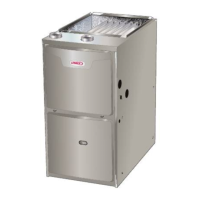
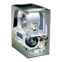
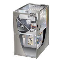
Diagram showing the location of major furnace components.

Unit Components

ESD Precautions

Procedures for handling components to prevent ESD damage.

Control Box Components

Details on transformer, door switch, circuit breaker, and ignition control.

Transformer, Door Switch, Circuit Breaker

Description of specific control box components.

Integrated Ignition Control

Description of the integrated ignition control system.

Ignition Control Details

Quick Connect Terminals

Lists and describes terminal connections for ignition control.

Diagnostic Codes

Table of diagnostic codes for ignition control 103217-03.

Ignition Control Operation

Electronic Ignition Process

Explains the sequence of electronic ignition.

Fan Timing Controls

Details heating and cooling fan on/off delay settings.

Ignition Control Status Codes

Diagnostic Codes (Table 5)

Lists diagnostic codes and statuses for ignition control 107163-01.

Heating Components

Flame Rollout Switches

Description and troubleshooting of flame rollout switches.

Heat Exchanger Description

Description of the heat exchanger assembly.

Component Details

Gas Valve Operation

Details on the gas valve and its operation.

Flame Sensor Measurement

Procedure for measuring flame signal and troubleshooting.

Ignitor Testing

Procedure for testing the ignitor's resistance and voltage.

Measuring Flame Signal

Flame Signal Measurement Procedure

Steps to measure flame signal using a digital meter.

Ignitor Testing Procedures

Test 1: Resistance Check

Checks ignitor circuit resistance via 4-pin plug.

Test 2: Resistance Check

Checks ignitor resistance at the 2-pin jack-plug.

Test 3: Voltage Check

Checks ignitor voltage during warm-up period.

Combustion Air System Components

Combustion Air Inducer Orifice Sizes

Table listing orifice sizes for various models.

Combustion Air Pressure Switch

Description and function of the pressure switch.

Measuring Pressure Differential

Pressure Differential Measurement Procedure

Steps for measuring pressure differential using a manometer.

Pressure Switch Troubleshooting

Common Pressure Switch Problems and Solutions

Table of common pressure switch issues and corrective actions.

Blower Compartment

Blower Balancing and Voltage

Notes on blower balancing and input voltage requirements.

Motor Troubleshooting

Troubleshooting steps for the blower motor.

Secondary Limit Controls

Description of secondary limit controls.

Motor Module Replacement

Motor Module Tests

Tests for motor module resistance and blower spin.

Motor Module Installation

Procedure for installing a replacement motor control module.

Placement and Installation

Pipe & Fittings Specifications

Details approved piping and fitting materials and standards.

Primer & Solvent Cement

Lists primer and solvent cement specifications.

Canadian Venting Systems

Lists approved venting systems for Canada.

Joint Cementing Procedure

Safety Warning: Fumes

Critical warning about flammable fumes from PVC glue.

Cementing Steps

Step-by-step guide for cementing pipe joints.

Venting Practices

Piping Suspension & Wall Thickness

Guidelines for pipe support and wall thickness.

Common Vent System Replacement

Instructions for replacing a furnace in a common vent system.

Exhaust Piping Installation

Guidance for routing and terminating exhaust piping.

Vent Piping Guidelines

Approved Venting Systems

Information on DuraVent and Centrotherm venting systems.

Vent Types and Sizing

Guidelines for intake and exhaust pipe sizing.

Piping Size Determination Process

Step-by-step process for determining correct pipe size.

Exhaust and Intake Pipe Connections (Upflow)

Exhaust and Intake Pipe Connections (Horizontal)

Diagrams for horizontal direct/non-direct vent pipe connections.

Intake Piping Installation

Direct Vent Intake Piping

Instructions for direct vent intake pipe routing.

Non-Direct Vent Intake Piping

Instructions for non-direct vent intake pipe routing.

Confined Space Installation Scenarios

Attic Installation

Installation details for equipment in a confined attic space.

Crawlspace Installation

Installation details for equipment in a confined crawlspace.

General Vent Termination Guidelines

Guidelines for vent termination placement and clearances.

Important Termination Notes

Important notes regarding termination practices.

Vent Termination Clearances (Non-Direct Vent)

USA Installation Clearances

Clearance requirements for US non-direct vent installations.

Canadian Installation Clearances

Clearance requirements for Canadian non-direct vent installations.

Vent Termination Clearances (Direct Vent)

USA Installation Clearances

Clearance requirements for US direct vent installations.

Canadian Installation Clearances

Clearance requirements for Canadian direct vent installations.

Direct Vent Piping Terminations

Piping Placement and Separation

Guidelines for intake/exhaust pipe placement and separation.

Roof and Side Wall Terminations

Details for roof and side wall vent terminations.

Vent Piping Installation Details

Side Wall Piping Support

Requirements for supporting side wall vent piping.

Multiple Furnace Installations

Guidance for installing multiple furnace terminations.

Field Fabricated Wall Terminations

Straight and Extended Applications

Details for straight and extended wall terminations.

Alternative Terminations

Details on alternative terminations using TEEs/elbows.

Non-Direct Vent Exhaust Piping

Piping Termination Requirements

Requirements for non-direct vent exhaust piping terminations.

Crawl Space Venting

Instructions for venting in crawl space applications.

Condensate Trap Installation

Trap and Plug Locations

Shows locations for condensate trap and plugs.

Remote Trap Locations

Diagrams for remote condensate trap locations.

Condensate Line Routing and Venting

Guidance on routing condensate lines and venting.

Condensate Drain Configurations

Condensate Trap with Overflow Switch

Diagram of trap with optional overflow switch.

Furnace with Separate Drain

Configuration for furnace with separate drain.

Furnace with Common Drain

Configuration for furnace with common drain.

Horizontal Drain Configurations

Separate Drain (Horizontal)

Drain configuration for horizontal discharge, separate drain.

Common Drain (Horizontal)

Drain configuration for horizontal discharge, common drain.

Important Combined Drain Note

Important note about venting combined drains.

Trap and Drain Assembly Details

12 PVC Assembly

Diagram for trap and drain assembly using 1/2" PVC.

34 PVC Assembly

Diagram for trap and drain assembly using 3/4" PVC.

Start-Up Procedures

Preliminary Checks

Initial checks before starting the furnace.

Heating Start-Up Steps

Steps for initiating heating operation.

Gas Leak Safety

Critical safety instruction regarding gas leak detection.

Furnace Operation

Procedure for placing the furnace into operation.

Condensate Trap Priming

Procedure for priming the condensate trap.

Gas Valve Operation

Steps for operating the gas valve.

Turning Off Gas

Procedure for turning off gas supply to the unit.

Failure to Operate Troubleshooting

Troubleshooting steps for furnace non-operation.

Heating System Service Checks

CSA Certification

Information on CSA design certification.

Gas Piping Requirements

Guidelines for gas piping installation.

Gas Leak Detection

Warning and recommended methods for gas leak detection.

Gas Supply Pressure Testing

Procedure for testing gas supply pressure.

Manifold Pressure Measurement

Procedure for measuring manifold pressure.

Combustion and Altitude Checks

Proper Combustion Analysis

Procedure for checking combustion CO2 levels.

High Altitude Considerations

Notes on installation at high altitudes and requirements.

Ground and Voltage Checks

Electrical Safety Warning

Warning regarding electrical shock hazard and grounding.

Voltage Measurement Procedure

Procedure for checking voltage at the integrated control.

Typical Operating Characteristics

Blower Operation and Adjustment

General procedure for blower operation and thermostat settings.

Temperature Rise

Explanation of temperature rise factors for ML196UH units.

External Static Pressure Measurement

Procedure for measuring external static pressure.

Blower Speed Taps

Information on changing blower speed tap settings.

Maintenance

General Safety Warnings

General safety warnings for performing maintenance.

Blower Maintenance

Instructions for checking and cleaning the blower wheel.

Filter Maintenance

Instructions for inspecting, cleaning, or replacing filters.

Wiring and Circuit Breaker Precautions

Warnings regarding wiring size and circuit breakers.

Winterizing and Condensate Trap Care

Condensate Hose Screens

Procedure for checking and cleaning condensate hose screens.

Heat Exchanger Cleaning Procedure

Detailed steps for cleaning the heat exchanger assembly.

Burner Assembly Cleaning

Leak Detection Caution

Caution regarding corrosive nature of some leak detection soaps.

Wiring Diagram and Sequence of Operation

Heating Units Wiring

Wiring diagram for heating units.

Troubleshooting: Heating Sequence

Normal vs. Abnormal Heating Modes

Flowchart detailing normal and abnormal heating sequences.

Heating Sequence of Operation Continued

Ignition and Flame Sensing Checks

Troubleshooting steps related to ignition and flame sensing.

Limit and Pressure Switch Checks

Troubleshooting steps for limit and pressure switches.

Cooling Sequence of Operation

Normal vs. Abnormal Cooling Modes

Flowchart detailing normal and abnormal cooling sequences.

Continuous Fan Accessories Operation

Fan Mode Operation

Sequence of operation for continuous fan and accessories.

Related product manuals