EasyManua.ls Logo

Lennox ML196UHE Series

Lennox ML196UHE Series
57 pages
To Next Page IconTo Next Page
To Previous Page IconTo Previous Page
Loading...
Page 19
C- Blower Compartment
IMPORTANT
Each blower is statically and dynamically balanced
as an assembly before installation in the unit.
       
     

   


Input Voltage Requirements



Troubleshooting
       

1 - 󰀨
 

NOTE - FIGURE 16 is typical ignition control
illustration.
           


         
    


         

9. Secondary Limit Controls
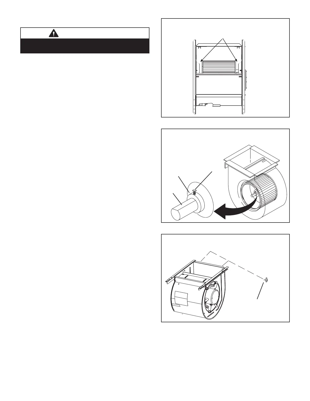





   -

Center Blower Wheel
in Blower Housing
BLOWER WHEEL REPLACEMENT
FIGURE 13
Set Screw
Housing Hub
ALIGN AND TIGHTEN SET SCREW WITH
FLAT SIDE OF MOTOR SHAFT
Motor
Shaft
FIGURE 14
SECONDARY LIMIT CONTROL
Secondary Limits
FIGURE 15

Related product manuals