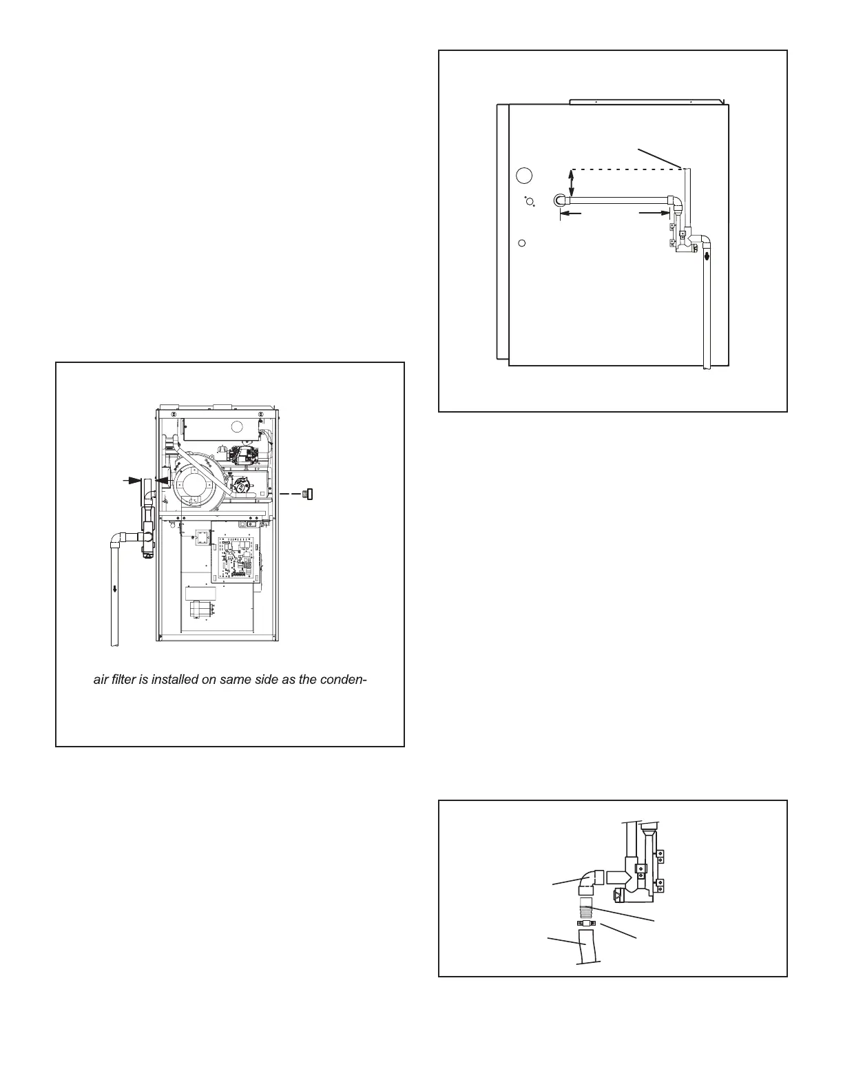
NOTE - If necessary the condensate trap may be installed
up to 5’ away from the furnace. Use PVC pipe to connect
trap to furnace condensate outlet. Piping from furnace
must slope down a minimum of 1/4” per ft. toward trap.
1 -
NOTE - Cold end header box drain plugs are factory
installed. Check the unused plug for tightness to
prevent leakage.
CONDENSATE TRAP AND PLUG LOCATIONS
(Unit shown in upflow position)
NOTE - In upflow applications where side return
sate trap, filter rack must be installed beyond
condensate trap or trap must be re-located to
Trap
(same on
right side)
Plug
(same on left side)
1-1/2 in.
FIGURE 46
(Unit shownin upflow position withremote trap)
*5’ max.
To Drain
PVCPipeOnly
FieldProvidedVent
Min.1” Above Condensate
Drain
Connection
1”
Min.
Trap CanBeInstalleda
Maximum 5’ From Furnac
e
2” Max.
CONDENSATE TRAP LOCATIONS
*Piping from furnace must slope down a
minimum 1/4” per ft. toward trap
FIGURE 47
Upow furnace (FIGURE 51)
Horizontal furnace
(FIGURE 52) -
NOTE - In horizontal applications it is recommended
to install a secondary drain pan underneath the unit
and trap assembly.
NOTE - Appropriately sized tubing and barbed tting
may be used for condensate drain. Attach to the
drain on the trap using a hose clamp. See FIGURE
48.
Field Provided Drain Components
Tubing
Hose Clamp
Barbed Fitting
Elbow
FIGURE 48
 Loading...