EasyManua.ls Logo

Lennox ML196UHE Series

Lennox ML196UHE Series
57 pages
To Next Page IconTo Next Page
To Previous Page IconTo Previous Page
Loading...
Page 16
7. Combustion Air Inducer & Cold End Header Box
        
        

-

   
        -
 

         
          
         
-


-


󰀨       If replacement
is necessary the gaskets used to seal the box to the
vestibule panel and the combustion air inducer to the
box, must also be replaced.
TABLE 6
Unit 
 
 
 
 
 
 
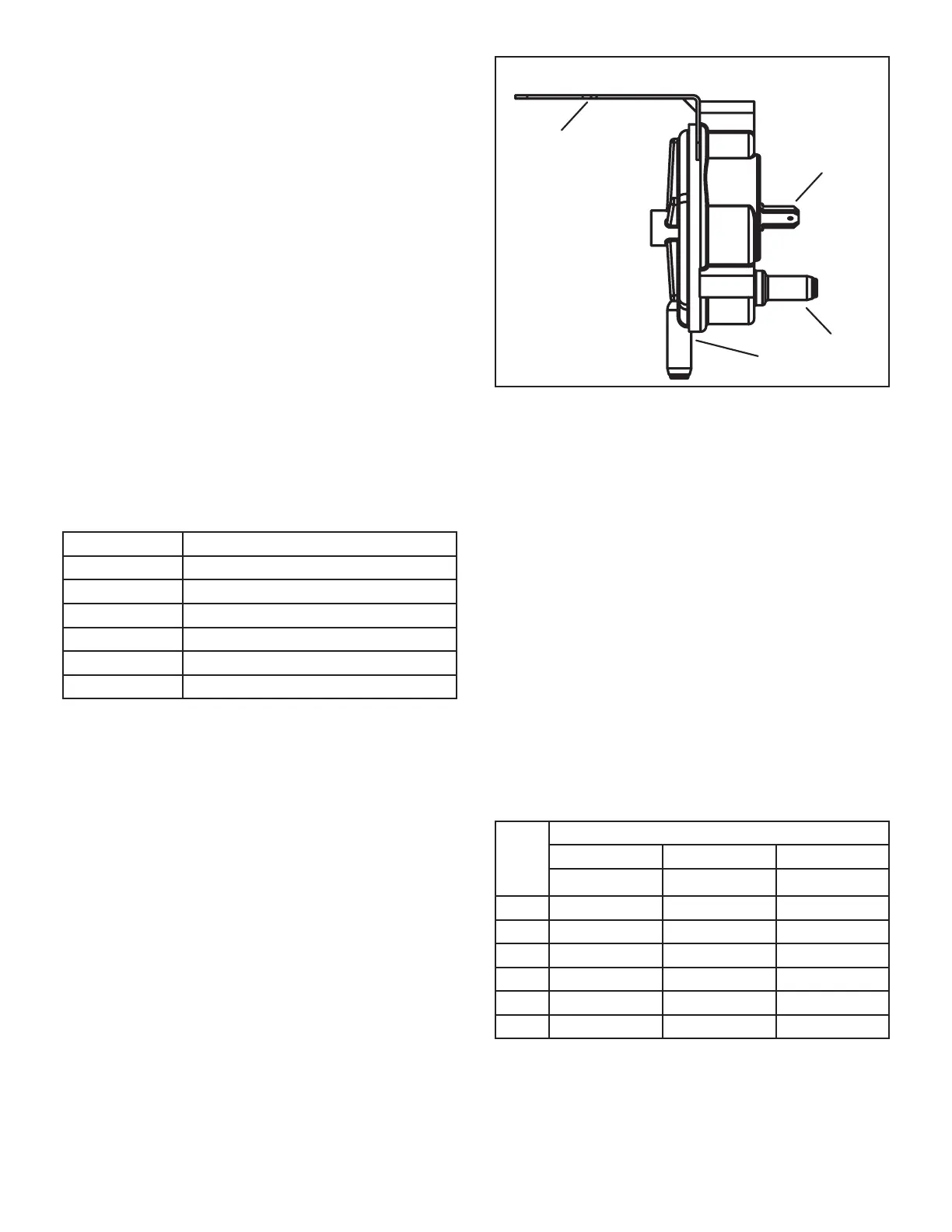
8. Combustion Air Pressure Switch (FIGURE 11)
       󰀨



        
    


Pressure Switch
24VAC
TERMINALS
BRACKET
TAP
TAP
FIGURE 11


 󰀨 -
-
-
󰀨

-


      󰀨 
        󰀨

   󰀨    -
     󰀨 

󰀨-
         


TABLE 7
Unit

  
  
   
   
   
   
   
   
*Set point is factory set and non-adjustable.

Related product manuals