Page 38
Thermostat Furnace Condensing
Unit
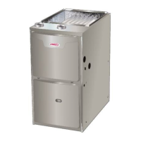
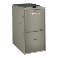
ML195UH and CONDENSING UNIT
THERMOSTAT DESIGNATIONS
(Refer to specific thermostat and outdoor unit.)
COMMON
POWER
HEAT
INDOOR BLOWER
Y
C
R
G
W1
Y
C
R
G
W
COOLING
FIGURE 57
CONDENSING
UNIT
CONDENSING
UNIT COMMON
*CONDENSING
UNIT
*NOTE − R" REQUIRED ON SOME OUTDOOR UNITS
Install the room thermostat according to the instruc-
tions provided with the thermostat. See figure 57 for
thermostat designations. If the furnace is being
matched with a heat pump, refer to the FM21 installa-
tion instruction or appropriate dual fuel thermostat in-
structions.
Indoor Blower Speeds
1 − When the thermostat is set to FAN ON," the indoor
blower will run continuously on the heating speed
when there is no cooling or heating demand.
2 − When the ML195UH is running in the heating mode,
the indoor blower will run on the heating speed.
3 − When there is a cooling demand, the indoor blower will
run on the cooling speed.
Generator Use − Voltage Requirements
The following requirements must be kept in mind when
specifying a generator for use with this equipment:
D The furnace requires 120 volts +
10% (Range: 108
volts to 132 volts).
D The furnace operates at 60 Hz +
5% (Range: 57 Hz to
63 Hz).
D The furnace integrated control requires both polarity
and proper ground. Both polarity and proper grounding
should be checked before attempting to operate the
furnace on either permanent or temporary power.
D Generator should have a wave form distortion of less
than 5% THD (total harmonic distortion).
TYPICAL ML195UH FIELD WIRING DIAGRAM
FIGURE 58
IGNITOR
*R
*NOTE − R" REQUIRED ON SOME OUTDOOR UNITS
 Loading...