Page 16
To Cold End Header Box
Field Provided Tubing
To Pressure Switch
To Cold End Header Box
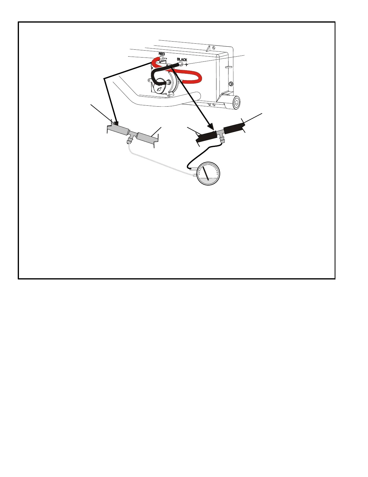
FIGURE 11
1 - Remove thermostat demand and allow unit to
cycle off.
2 - Install a tee in the negative (-) line (red and black tubing
or red tubing) and a tee in the positive (+) line (black
tubing) running from the pressure switch to the cold
end header box.
3 - Install a manometer with hose from the negative (-)
side of the manometer to the tee installed in the
negative (-) line and with hose from the positive (+)
side of the manometer to the tee in the positive (+)
line.
NOTE - Both sides of the cold end header box are nega
tive. However the (+) port reads less negative pressure
than the (-) port.
4 - Operate unit and observe manometer reading.
Readings will change as heat exchanger warms.
a. Take one reading immediately after start‐up.
b. Take a second reading after unit has reached
steady state (approximately 5 minutes). This will be
the pressure differential.
The pressure differential should be greater
than those listed in table 6.
5 - Remove thermostat demand and allow to cycle off.
6 - Remove manometer and tee's. Reinstall combustion
air sensing hoses to the pressure switch.
Measuring Pressure Differential
Black Tubing
(positive +)
Red and Black Tubing
or Red Tubing
(negative -)
“+”
High
“-”
Low
 Loading...