Page 38
NOTE - Cold end header box drain plugs are factory in
stalled. Check the unused plug for tightness to prevent
leakage.
3 - Install the cap over the clean out opening at the base
of the trap. Secure with clamp. See figure 53.
4 - Install drain trap using appropriate PVC fittings, glue
all joints. Glue the provided drain trap as shown in fig
ure 53. Route the condensate line to an open drain.
Condensate line must maintain a 1/4” downward slope
from the furnace to the drain.
FIGURE 45
CONDENSATE TRAP AND PLUG LOCATIONS
(Unit shown in upflow position)
NOTE - In upflow applications where side return
air filter is installed on same side as the conden
sate trap, filter rack must be installed beyond
condensate trap or trap must be re-located to
avoid interference.
Trap
(same on
right side)
Plug
(same on left side)
1-1/2 in.
5 - Figures 48 and 50 show the furnace and evaporator
coil using a separate drain. If necessary the conden
sate line from the furnace and evaporator coil can
drain together. See figures 49, 51 and 52.
Upflow furnace (figure 51) - In upflow furnace applica
tions the field provided vent must be a minimum 1” to a
maximum 2” length above the condensate drain outlet
connection. Any length above 2” may result in a flood
ed heat exchanger if the combined primary drain line
were to become restricted.
Horizontal furnace (figure 52) - In horizontal furnace
applications the field provided vent must be a mini
mum 4” to a maximum 5” length above the condensate
drain outlet connection. Any length above 5” may re
sult in a flooded heat exchanger if the combined pri
mary drain line were to become restricted.
NOTE - In horizontal applications it is recommended to
install a secondary drain pan underneath the unit and
trap assembly.
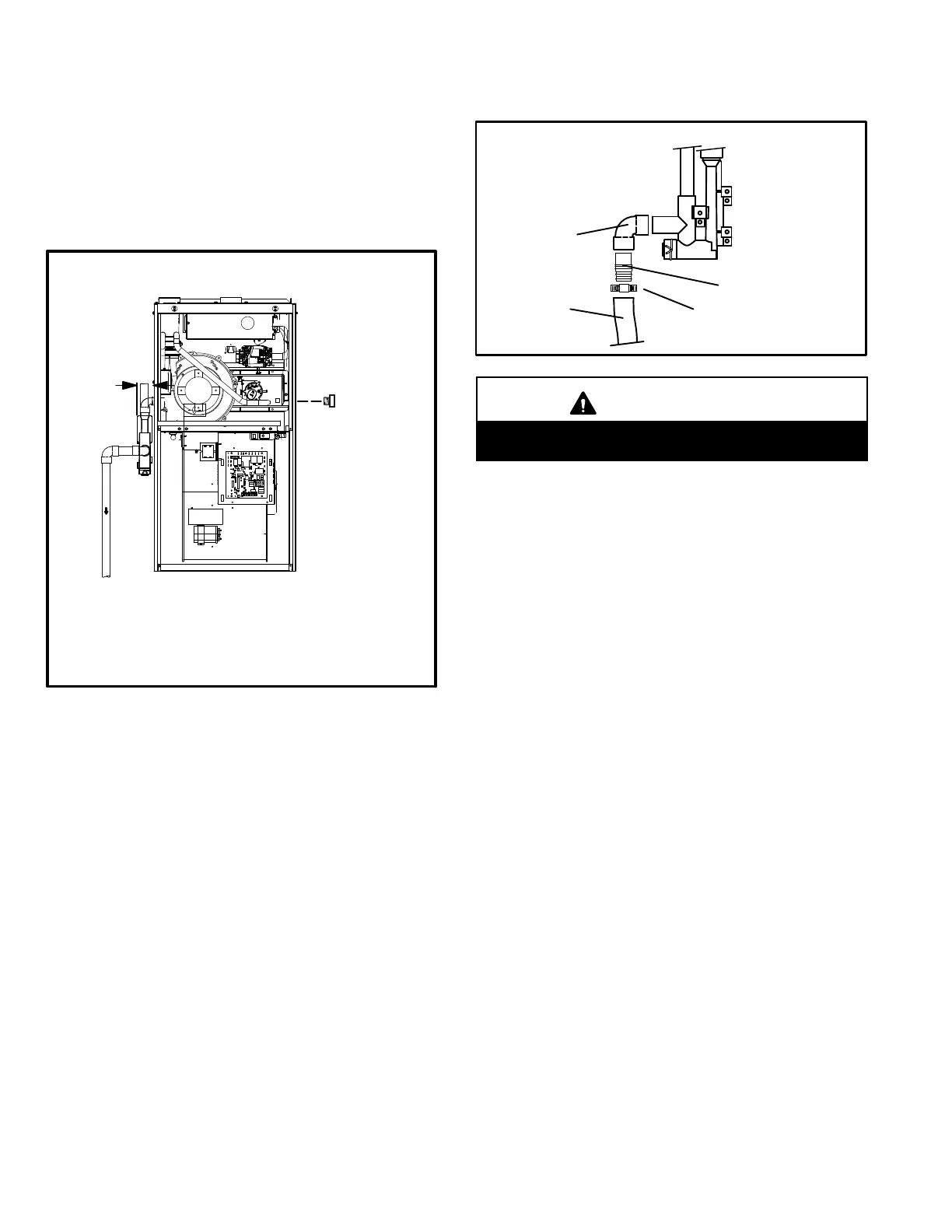
NOTE - Appropriately sized tubing and barbed fitting may
be used for condensate drain. Attach to the drain on the
trap using a hose clamp. See figure 46.
FIGURE 46
Tubing
Hose Clamp
Barbed Fitting
Field Provided Drain Components
Elbow
CAUTION
Do not use copper tubing or existing copper conden
sate lines for drain line.
6 - If unit will be started immediately upon completion of in
stallation, prime trap per procedure outlined in Unit Start-
Up section.
Condensate line must slope downward away from the
trap to drain. If drain level is above condensate trap,
condensate pump must be used. Condensate drain
line should be routed within the conditioned space to
avoid freezing of condensate and blockage of drain
line. If this is not possible, a heat cable kit may be used
on the condensate trap and line. Heating cable kit is
available from Lennox in various lengths; 6 ft. (1.8m) -
kit no. 26K68 and 24 ft. (7.3m) - kit no. 26K69.
 Loading...