Page 36
7 - If intake and exhaust piping must be run up a side
wall to position above snow accumulation or other
obstructions, piping must be supported. At least
one bracket must be used within 6” from the top of
the elbow and then every 24” (610mm) as shown
in FIGURE 37, to prevent any movement in any
direction. When exhaust and intake piping must
be run up an outside wall, the exhaust piping must
be terminated with pipe sized per TABLE 17.The
intake piping may be equipped with a 90° elbow
turndown. Using turndown will add 5 feet (1.5m) to
the equivalent length of the pipe.
8 - - A multiple furnace installation may use a group
of up to four terminations assembled together
horizontally, as shown in FIGURE 35.
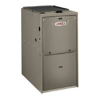
PIPE1” EXTENSION FOR 3”
PVC PIPE
1-1/2” ACCELERATOR
FURNACE
EXHAUST
PIPE
FURNACE
INTAKE
PIPE
4''
GLUE EXHAUST
END FLUSH INTO
TERMINATION
FLAT
SIDE
FLUSH-MOUNT SIDE WALL TERMINATION KIT
51W11 (US) or 51W12 (Canada)
FIGURE 32
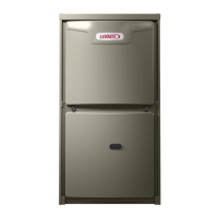
DIRECT VENT CONCENTRIC ROOFTOP TERMINATION
71M80, 69M29 or 60L46 (US)
44W92 or 44W93 (Canada)
Minimum
Above Average
Snow
Accumulation
SHEET METAL STRAP
(Clamp and sheet metal strap
must be field installed to support
the weight of the termination kit.)
FLASHING
(Not Furnished)
CLAMP
FIELD-PROVIDED
REDUCER MAY BE REQUIRED
TO ADAPT DIFFERENT VENT
PIPE SIZE TO TERMINATION
INTAKE
Accelerator not required for
3” concentric
12” (305mm)
FIGURE 33
12” (305mm) Min.
above grade or
average snow ac
cumulation.
DIRECT VENT CONCENTRIC WALL TERMINATION
71M80, 69M29 or 60L46 (US)
44W92 or 44W93 (Canada)
INTAKE
AIR
EXHAUST
AIR
INTAKE
AIR
INTAKE
AIR
EXHAUST
AIR
OUTSIDE
WALL
GRADE
CLAMP
(Not Furnished)
FIELD-PROVIDED
REDUCER MAY BE
REQUIRED TO ADAPT
DIFFERENT VENT PIPE
SIZE TO TERMINATION
Accelerator not required
for 3” concentric
FIGURE 34
EXHAUST
VENT
INTAKE
AIR
5-1/2”
(140mm)
Front View
12”
(305mm)
5”
(127mm)
18” MAX.
(457mm)
EXHAUST VENT
INTAKE
AIR
OPTIONAL VENT TERMINATION FOR MULTIPLE UNIT
INSTALLATION OF DIRECT VENT WALL TERMINATION KIT
Inches (mm)
Side View
12” (305mm) Min.
above grade or
cumulation.
optional intake elbow
FIGURE 35
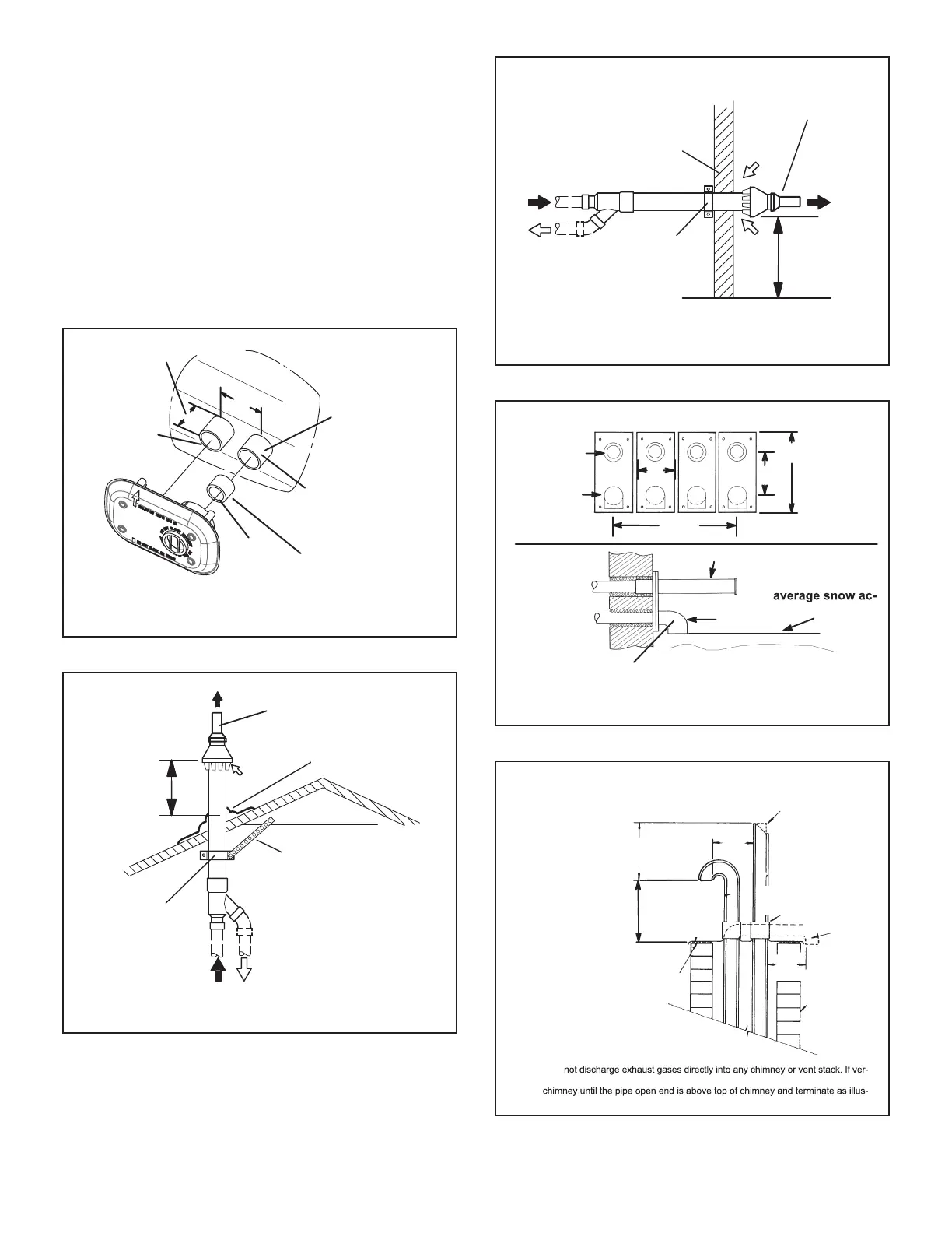
USING EXISTING CHIMNEY
NOTE - Do
tical discharge through an existing unused chimney or stack is required, insert piping
inside
trated. In any exterior portion of chimney, the exhaust vent must be insulated.
8” - 12”
(203mm - 305mm)
3” - 8”
(76mm-
203mm)
3” - 8”
(76mm-
203mm)
STRAIGHT-CUT OR
ANGLE-CUT IN DIRECTION
OF ROOF SLOPE *
SHOULDER OF FITTINGS
PROVIDE SUPPORT
OF PIPE ON TOP PLATE
ALTERNATE
INTAKE PIPE
INTAKE PIPE
INSULATION (optional)
EXTERIOR
PORTION OF
CHIMNEY
INSULATE
TO FORM
SEAL
SHEET
METAL TOP
PLATE
Minimum 12” (305MM)
above chimney top
plate or average snow
accumulation
FIGURE 36
 Loading...