Page 43
III-START-UP
A-Preliminary and Seasonal Checks
1 - Inspect electrical wiring, both eld and factory
installed for loose connections. Tighten as required.
2 - Check voltage at disconnect switch. Voltage must
be within range listed on the nameplate. If not,
consult the power company and have voltage
condition corrected before starting unit.
3 - Inspect condition of condensate traps and drain
assembly. Disassemble and clean seasonally.
B-Heating Start-Up
BEFORE LIGHTING the unit, smell all around the furnace
area for gas. Be sure to smell next to the oor because
some gas is heavier than air and will settle on the oor.
The gas valve on the ML296DFV is equipped with a gas
control switch. Use only your hand to move the switch.
Never use tools. If the the switch will not move by hand,
replace the valve. Do not try to repair it. Force or attempt-
ed repair may result in a re or explosion.
Placing the furnace into operation:
ML296DFV units are equipped with a SureLight
®
ignition
system. Do not attempt to manually light burners on this
furnace. Each time the thermostat calls for heat, the burn-
ers will automatically light The ignitor does not get hot
when there is no call for heat on units with SureLight igni-
tion system.
Priming Condensate Trap
The condensate trap should be primed with water prior
to start-up to ensure proper condensate drainage. Either
pour 10 . oz. (300 ml) of water into the trap, or follow
these steps to prime the trap:
1 - Follow the lighting instructions to place the unit into
operation.
2 - Set the thermostat to initiate a heating demand.
3 - Allow the burners to re for approximately 3 minutes.
4 - Adjust the thermostat to deactivate the heating
demand.
5 - Wait for the combustion air inducer to stop. Set the
thermostat to initiate a heating demand and again
allow the burners to re for approximately 3 minutes.
6 - Adjust the thermostat to deactivate the heating
demand and again wait for the combustion air
inducer to stop. At this point, the trap should be
primed with sucient water to ensure proper
condensate drain operation.
WARNING
If you do not follow these instructions exactly, a re
or explosion may result causing property damage,
personal injury or death.
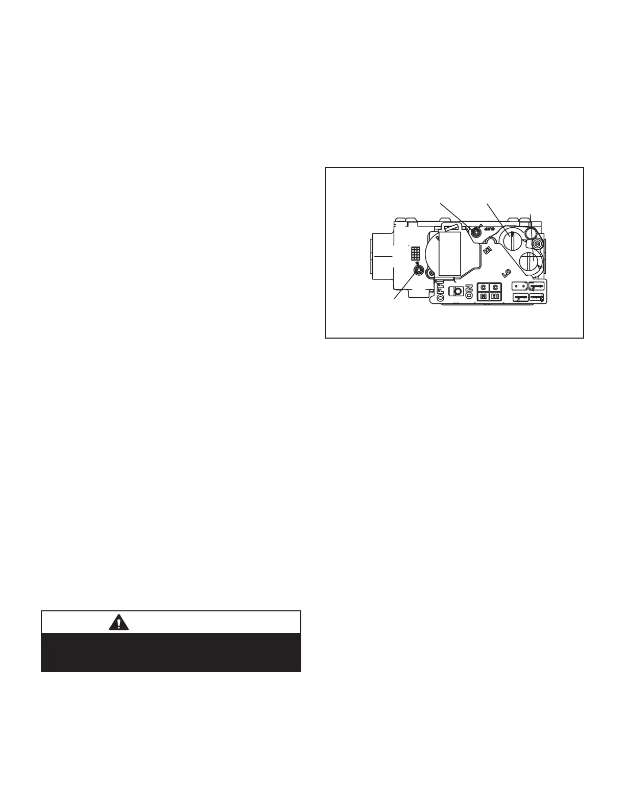
Gas Valve Operation (FIGURE 50)
1 - STOP! Read the safety information at the beginning
of this section.
2 - Set the thermostat to the lowest setting.
3 - Turn o all electrical power to the unit.
4 - This furnace is equipped with an ignition device
which automatically lights the burners. Do not try to
light the burners by hand.
5 - Remove the upper access panel.
6 - Move gas valve switch to OFF. See FIGURE 50.
7 - Wait ve minutes to clear out any gas. If you then
smell gas, STOP! Immediately call your gas supplier
from a neighbor’s phone. Follow the gas supplier’s
instructions. If you do not smell gas go to next step.
8 - Move gas valve switch to ON. See FIGURE 50.
GAS VALVE SHOWN IN ON POSITION
INLET PRESSURE POST
HIGH FIRE
ADJUSTMENT
(under cap)
MANIFOLD
PRESSURE TAP
LOW FIRE
ADJUSTMENT
(under cap)
FIGURE 50
9 - Replace the upper access panel.
10 - Turn on all electrical power to to the unit.
11 - Set the thermostat to desired setting.
NOTE - When unit is initially started, steps 1 through
11 may need to be repeated to purge air from gas
line.
12 - If the appliance will not operate, follow the
instructions “Turning O Gas to Unit” and call your
service technician or gas supplier.
Turning O Gas to Unit
1 - Set the thermostat to the lowest setting.
2 - Turn o all electrical power to the unit if service is to
be performed.
3 - Remove the upper access panel.
4 - Move gas valve switch to OFF.
5 - Replace the upper access panel.
Failure To Operate
If the unit fails to operate, check the following:
1 - Is the thermostat calling for heat?
2 - Are access panels securely in place?
3 - Is the main disconnect switch closed?
4 - Is there a blown fuse or tripped breaker?
5 - Is the lter dirty or plugged? Dirty or plugged lters
will cause the limit control to shut the unit o.
6 - Is gas turned on at the meter?
7 - Is the manual main shut-o valve open?
8 - Is the internal manual shut-o valve open?
9 - Is the unit ignition system in lockout? If the unit
locks out again, inspect the unit for blockages.
 Loading...