Page 47
V-TYPICAL OPERATING CHARACTERISTICS
A-Blower Operation and Adjustment
1 - Blower operation is dependent on thermostat control
system.
2 - Generally, blower operation is set at thermostat
subbase fan switch. With fan switch in ON position,
blower operates continuously. With fan switch in
AUTO position, blower cycles with demand or runs
continuously while heating or cooling circuit cycles.
3 - Depending on the type of indoor thermostat, blower
and entire unit will be o when the system switch is
in OFF position.
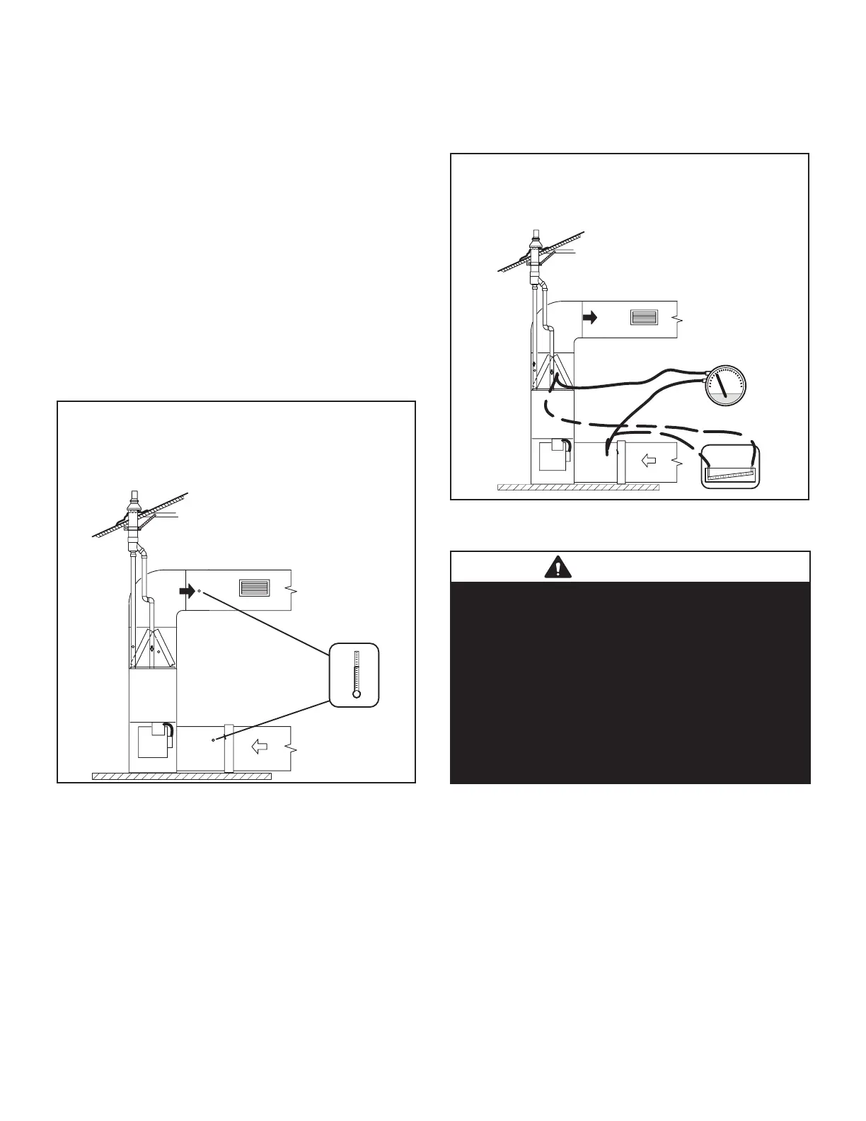
B-Temperature Rise (FIGURE 53)
Temperature rise for ML296UHV units depends on unit in-
put, blower speed, blower horsepower and static pressure
as marked on the unit rating plate. The blower speed must
be set for unit operation within the range of “TEMP. RISE
°F” listed on the unit rating plate.
°
TEMPERATURE RISE
Supply Duct Temperature ________
Return Duct Temperature
_
_____
Temperature Rise = ________
SUPPLY
AIR
Temperatures
RETURN AIR
FIGURE 53
C-External Static Pressure
1 - Tap locations shown in FIGURE 54.
2 - Punch a 1/4” diameter hole in supply and return
air plenums. Insert manometer hose ush with
inside edge of hole or insulation. Seal around the
hose with permagum. Connect the zero end of the
manometer to the discharge (supply) side of the
system. On ducted systems, connect the other end
of manometer to the return duct as above.
3 - With only the blower motor running and the
evaporator coil dry, observe the manometer reading.
Adjust blower motor speed to deliver the air desired
according to the job requirements.
For heating speed (second stage heat speed)
external static pressure drop must not be more than
0.8” W.C. For cooling speed (second stage cool
speed) external static pressure drop must not be
more than 1.0” W.C.
4 - Seal the hole when the check is complete.
Supply Duct Static ________
Return Duct Static + _____
Total Duct Static = ________ (dry coil)
Duct Static
or
Supply Air
Return Air
FIGURE 54
VI-MAINTENANCE
WARNING
ELECTRICAL SHOCK, FIRE,
OR EXPLOSION HAZARD.
Failure to follow safety warnings exactly could
result in dangerous operation, serious injury, death
or property damage.
Improper servicing could result in dangerous
operation, serious injury, death, or property damage.
Before servicing, disconnect all electrical power to
furnace.
When servicing controls, label all wires prior
to disconnecting. Take care to reconnect wires
correctly. Verify proper operation after servicing.
At the beginning of each heating season, system should
be checked as follows by a qualied service technician:
Blower
Check the blower wheel for debris and clean if necessary.
The blower motors are prelubricated for extended bearing
life. No further lubrication is needed.
Filters
All air lters are installed external to the unit. Filters should
be inspected monthly. Clean or replace the lters when
necessary to ensure proper furnace operation. TABLE 23
lists recommended lter sizes.
 Loading...