Page 39
Condensate Piping
This unit is designed for either right‐ or left‐side exit of con
densate piping in upflow applications. In horizontal applica
tions, the condensate trap must extend below the unit. An
8” service clearance is required for the condensate trap.
Refer to figures 40 and 42 for condensate trap locations.
Figure 48 shows trap assembly using 1/2” PVC or 3/4”
PVC.
NOTE - If necessary the condensate trap may be installed
up to 5’ away from the furnace. Use PVC pipe to connect
trap to furnace condensate outlet. Piping from furnace
must slope down a minimum of 1/4” per ft. toward trap.
1 - Determine which side condensate piping will exit the
unit, location of trap, field-provided fittings and length of
PVC pipe required to reach available drain.
2 - Use a large flat head screw driver or a 1/2” drive socket
extension and remove plug (figure 40) from the cold
end header box at the appropriate location on the side
of the unit. Install provided 3/4 NPT street elbow fitting
into cold end header box. Use Teflon tape or appropri
ate pipe dope.
NOTE - Cold end header box drain plugs are factory in
stalled. Check the unused plug for tightness to prevent
leakage.
3 - Install the cap over the clean out opening at the base
of the trap. Secure with clamp. See figure 48.
4 - Install drain trap using appropriate PVC fittings, glue
all joints. Glue the provided drain trap as shown in fig
ure 48. Route the condensate line to an open drain.
Condensate line must maintain a 1/4” downward slope
from the furnace to the drain.
5 - Figures 43 and 44 show the furnace and evaporator
coil using a separate drain. If necessary the conden
sate line from the furnace and evaporator coil can
drain together. See figures 45, 46 and 47.
Upflow furnace (figure 46) - In upflow furnace applica
tions the field provided vent must be a minimum 1” to a
maximum 2” length above the condensate drain outlet
connection. Any length above 2” may result in a
flooded heat exchanger if the combined primary drain
line were to become restricted.
Horizontal furnace (figure 47) - In horizontal furnace
applications the field provided vent must be a mini
mum 4” to a maximum 5” length above the condensate
drain outlet connection. Any length above 5” may re
sult in a flooded heat exchanger if the combined pri
mary drain line were to become restricted.
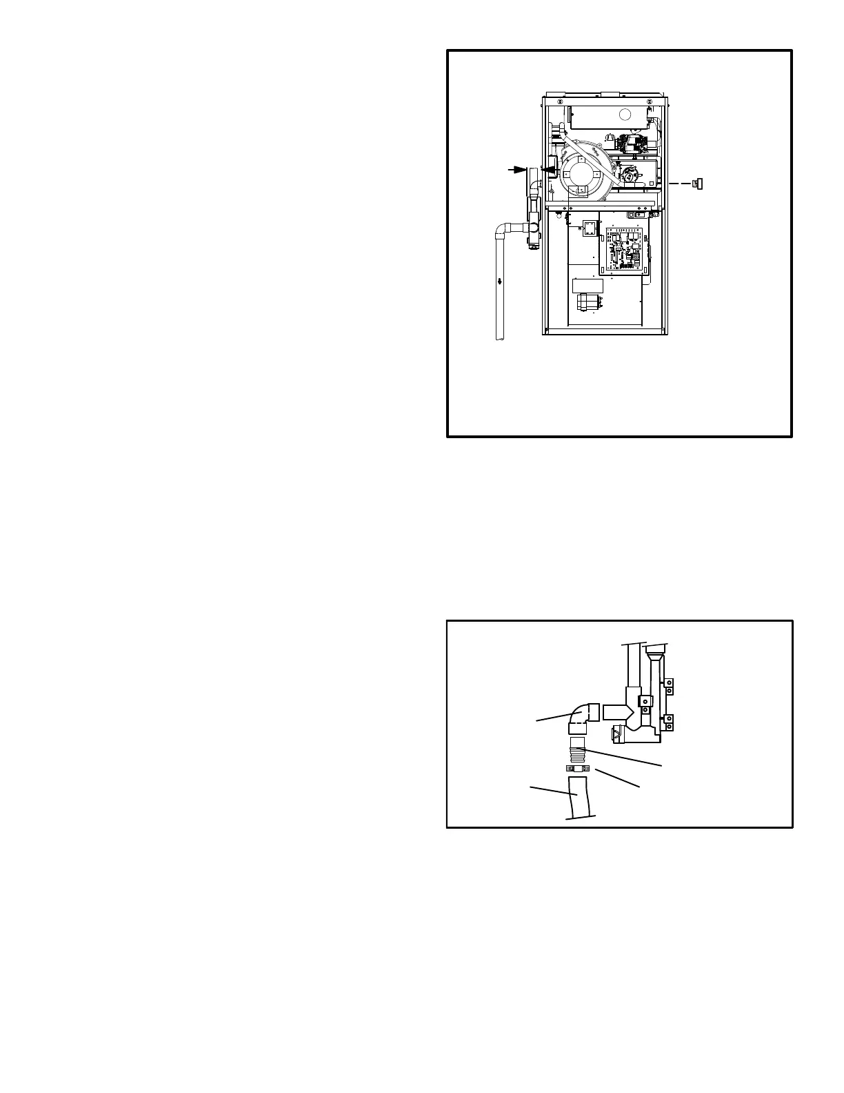
FIGURE 40
CONDENSATE TRAP AND PLUG LOCATIONS
(Unit shown in upflow position)
NOTE - In upflow applications where side return
air filter is installed on same side as the conden
sate trap, filter rack must be installed beyond
condensate trap or trap must be re-located to
avoid interference.
Trap
(same on
right side)
Plug
(same on left side)
1-1/2 in.
NOTE - In horizontal applications it is recommended to
install a secondary drain pan underneath the unit and
trap assembly.
NOTE - Appropriately sized tubing and barbed fitting
may be used for condensate drain. Attach to the drain
on the trap using a hose clamp. See figure 41.
FIGURE 41
Tubing
Hose Clamp
Barbed Fitting
Field Provided Drain Components
Elbow
 Loading...