Page 16
C- Heating Components
1. Ignitor
The ignitor is made of durable silicon nitride. Ignitor longev
ity is enhanced by controlling voltage to the ignitor. The in
tegrated control provides a regulated 120 volts to the igni
tor for a consistent ignition and long ignitor life. Ohm value
should be 39 to 70. See figure 11 for ignitor location and fig
ure 12 for ignitor check out.
NOTE - The ML296UHV(X) furnace contains electronic
components that are polarity sensitive. Make sure that the
furnace is wired correctly and is properly grounded.
2. Flame Sensor
A flame sensor is located on the left side of the burner sup
port. See figure 11. The sensor tip protrudes into the flame
envelope of the left-most burner. The sensor can be re
moved for service without removing any part of the burn
ers. During operation, flame is sensed by current passed
through the flame and sensing electrode. The SureLight
control allows the gas valve to remain open as long as
flame signal is sensed. See table 6 for flame signal.
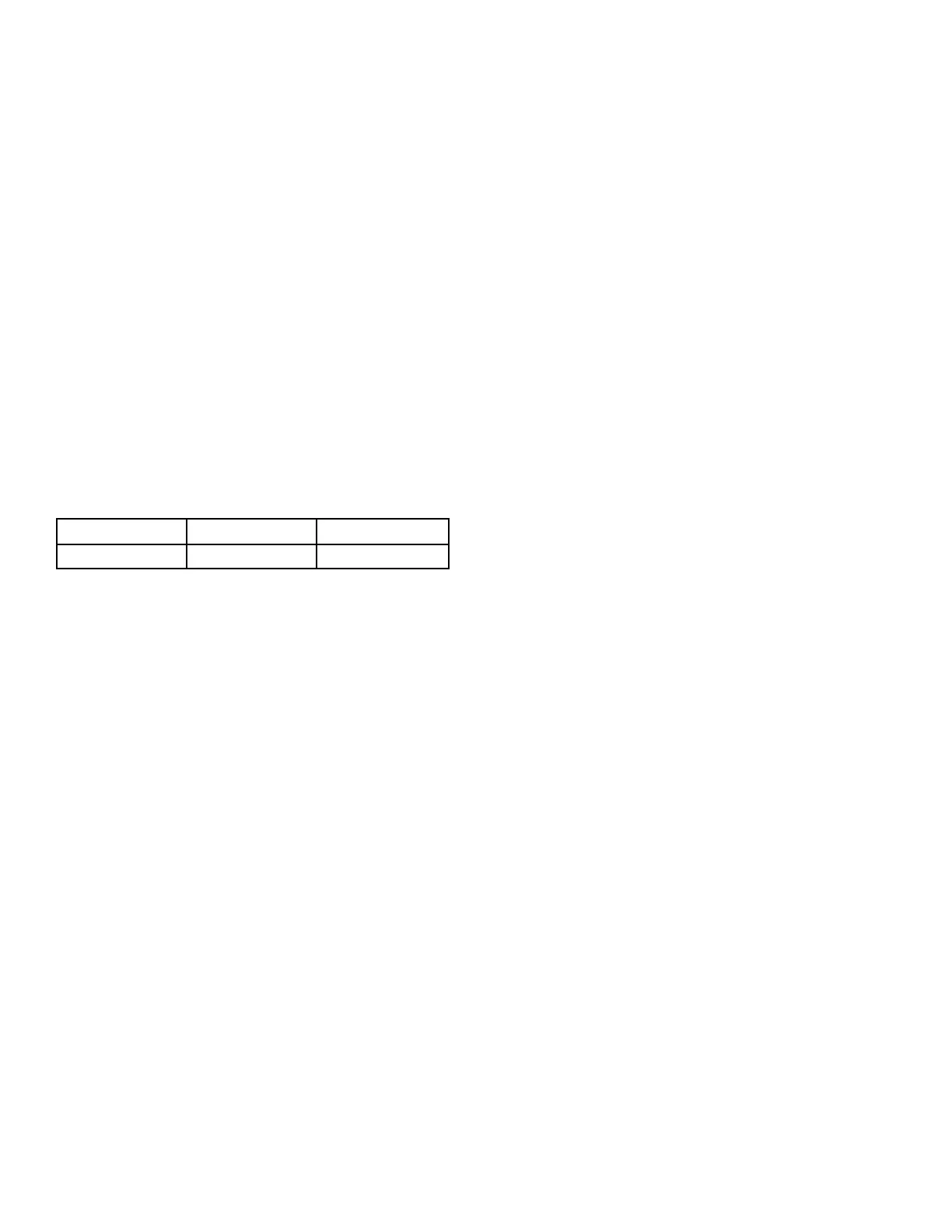
TABLE 6
Flame Signal in Microamps
Normal
Low Drop Out
1.5 or greater 1.0 or less 0.5
3. Gas Valve
The valve (figure 49) is internally redundant to assure safe
ty shut-off. If the gas valve must be replaced, the same type
valve must be used.
24VAC terminals and gas control knob are located on the
valve. A wire harness connects the terminals from the gas
valve to the electronic ignition control. 24V applied to the termi
nals energizes the valve.
Inlet and outlet pressure taps are located on the valve. A regu
lator adjustment screw is located on the valve.
LPG change over kits are available from Lennox. Kits include
burner orifices and a gas valve.
4. Flame Rollout Switches (S47)
Flame rollout switch is a high temperature limit located on
top of the burner box, one on each side.- See figure 11. The
limit is a N.C. SPST manual‐reset limit. When S47 senses
rollout, the circuit breaks and the ignition control immedi
ately stops ignition and closes the gas valve. Rollout can be
caused by a blocked heat exchanger, flue or lack of com
bustion air. The switch is factory set to trip (open) at 210°F
and cannot be adjusted. The switch can be manually reset.
To manually reset a tripped switch, push the reset button lo
cated on the control.
5. Burners
All units use inshot burners. Burners are factory set and re
quire no adjustment. Always operate the unit with the burner
box front panel in place. Each burner uses an orifice (see
table 21 for orifice size) that is precisely matched to the burn
er input. Burners can be removed as a one piece assembly
for service. If burner assembly has been removed, it is critical
to align center of each burner to the center of the clamshell
when re-installing. See more detail in Section VI- MAINTE
NANCE.
6. Primary Limit Control (S10)
The primary limit (S10) is located in the heating vestibule pan
el. When excess heat is sensed in the heat exchanger, the
limit will open. If the limit is open, the furnace control energizes
the supply air blower and closes the gas valve. The limit auto
matically resets when unit temperature returns to normal. The
switch must reset within three minutes or the SureLight control
will go into Watch guard for one hour. The switch is factory
set and cannot be adjusted. The switch may have a different
set point for each unit model number. See Lennox Repair
Parts Handbook if limit switch must be replaced,
 Loading...