39
NOTE: DIAGRAMS & ILLUSTRATIONS ARE NOT TO SCALE.
LENNOX HEARTH PRODUCTS • MERIT PLUS
®
DIRECT VENT GAS FIREPLACES (MPDP35/40) • INSTALLATION INSTRUCTIONS
Figure 63
Step 12. Reassemble the remaining compo-
nents by reversing the procedures outlined in
the preceding steps.
Step 13. Attach the conversion label provided
in the conversion kit next to the rating plate on
the appliance.
Step 14. Turn on gas supply and test for gas
leaks (refer to Page 28).
Step 15. Relight the main burner. The lighting
instructions can be found on the lighting label
in the control compartment or in the Care and
Operation Manual provided with the appliance.
Verify proper burner ignition and operation.
See Burner Adjustments and Burner Flame
Appearance on Pages 32 and 33.
Inspect the pilot system for proper flame. The
pilot flame should engulf the flame sensor as
shown in Figure 53 on Page 28.
Step 16. Using a manometer, test the inlet and
manifold gas pressures. See Tables 2 and 3 on
Page 4 and Figure 64.
ALWAYS TEST PRESSURES WITH THE VALVE
REGULATOR CONTROL AT THE HIGHEST
SETTING.
Step 11. Replace Burner Orifice
A. Remove the orifice from the manifold and
replace it with the one provided in the kit.
See Table 9 for orifice sizes for natural and
propane models. Figure 65 illustrates the ori-
fice. Use pipe joint compound or Teflon tape
on all pipe fittings before installing (ensure
propane resistant compounds are used in
propane applications, do not use pipe joint
compounds on flare fittings).
B. Retrieve the burner and hold the venturi tube
above the orifice. Place the shutter adjusting
rod in the slot of the shutter arm (see Figure 61
on Page 34). Set the burner assembly into its
position and secure the burner assembly with
the two screws previously removed.
Figure 65
Burner Orifice Sizes
Elevation 0-4500 feet ( 0-1372 meters)
Model Nat.Gas
drill size (inches)
Propane
drill size (inches)
MPDP35
#42 (.093")*
H3721•
#54 (.055")*
99K79•
MPDP40
#36 (.1065")*
18L40•
#52 (.063")*
21L01•
Table 9
* Standard size installed at factory
• Part /Cat. Number
Step 5. On the left side of the burner, remove
the two securing screws. Remove the burner
assembly.
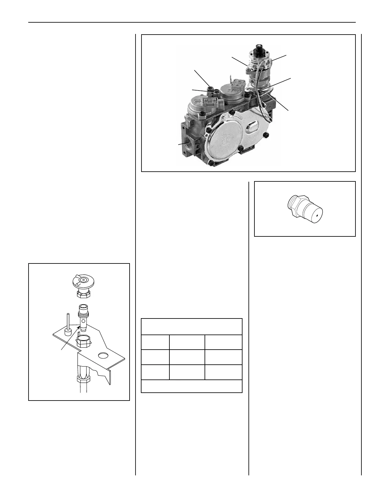
Step 6. Refer to Figure 64 and the instructions
provided with the SIT Regulator Conversion
Kit. Using a Torx T20 (with 1/4” shank and
center hole) or slotted screwdriver, remove and
discard the two (2) pressure regulator mount-
ing screws, pressure regulator tower, the
diaphragm assembly (A) (if applicable) and the
spring (B). Discard all removed components.
Ensure the rubber gasket (C), which is pre-
fitted as part of the assembly, is properly
positioned (see Figure 64).
Step 7. Install the new Stepper Motor pres-
sure regulator assembly using the supplied
screws as shown in Figure 64. Tighten screws
securely (reference torque = 25 lb. in.).
Step 8. Install the enclosed identification label
to the valve body where it can be easily seen.
Step 9. Make Stepper Motor and valve electri-
cal connections.
Step 10. See Figure 63 and replace the pilot
orifice. Remove the pilot hood assembly to
access the hexed pilot orifice. Remove and re-
place the orifice with the one provided with the
kit. Exercise extreme care to prevent damage to
or breakage of the igniter assembly.
Figure 64
Pressure
Regulator
Tower
Pressure Regulator
Mounting Screws
(Torx-T20)
Connect GTMS
Wire Harness
(A) Remove Diaphragm
(B) Remove Spring
Install New:
Pressure Regulator Tower
(C) Rubber Gasket
Inlet (In) Test Port
Manifold (Out)
Test Port
Pilot Orifice
size
Main Gas Inlet
3/8" NPT
 Loading...