EasyManua.ls Logo

Lennox MPD-4035CNM-B User Manual

Lennox MPD-4035CNM-B
42 pages
To Next Page IconTo Next Page
Page #1 background imageLoading...
Page #1 background image
MODELS
OTL Report No. 116-F-13-4
US
Portland
This appliance may be installed in an aftermarket permanently located, manufactured home (USA only) or mobile
home, where not prohibited by local codes. This appliance is only for use with the type of gas indicated on the rating
plate. This appliance is not convertible for use with other gases, unless a certified kit is used.
INSTALLATION INSTRUCTIONS
MPD Direct-Vent
Gas Fireplaces
MILLIVOLT:
ELECTRONIC:
MPDT-3328CNM-B
MPDT-3328CPM-B
MPDR-3328CNM-B
MPDR-3328CPM-B
MPD-3530CNM-B
MPD-3530CPM-B
MPD-4035CNM-B
MPD-4035CPM-B
MPD-4540CNM-B
MPD-4540CPM-B
MPDT-3328CNE-B
MPDT-3328CPE-B
MPDR-3328CNE-B
MPDR-3328CPE-B
MPD-3530CNE-B
MPD-3530CPE-B
MPD-4035CNE-B
MPD-4035CPE-B
MPD-4540CNE-B
MPD-4540CPE-B
P/N 850014 Rev. V 08/2011
This manual is one of a set of two supporting this product.
Refer to P/N 875014M for Care and Operation Instructions.
Ce manuel est disponible en francais, simplement
en faire la demande. Numéro de la pièce 850014CF.
Please read and understand these instructions
before starting installation.
INSTALLER: Leave this manual with the appliance.
CONSUMER: Retain this manual for future reference.
INSTALLATEUR : Laissez cette notice avec l’appareil.
CONSOMMATEUR : Conservez cette notice pour
consultation ultérieure.
AVERTISSEMENT : Assurez-vous de bien suivre les
instructions données dans cette notice pour réduire au
minimum le risque d’incindie ou d’explosion ou pour
éviter tout dommage matériel, toute blessure ou la mort.
WARNING: If the information in these instructions
is not followed exactly, a fire or explosion may
result, causing property damage, personal injury,
or death.
WARNING
/
AVERTISSEMENT
/
AVISO
HOT GLASS WILL CAUSE
BURNS.
DO NOT TOUCH GLASS
UNTIL COOLED.
NEVER ALLOW CHILDREN
TO TOUCH GLASS.
UNE SURFACE VITRÉE CHAUDE
PEUT CAUSER DES BRÛLURES.
LAISSER REFROIDIR LA SURFACE
VITRÉE AVANT D'Y TOUCHER.
NE PERMETTEZ JAMAIS À UN ENFANT
DE TOUCHER LA SURFACE VITRÉE.
EL VIDRIO CALIENTE
CAUSARÁ QUEMADURAS.
USTED DEBE NUNCA
TOCAR EL VIDRIO CALIENTE.
LOS NIÑOS DEBEN NUNCA
TOCAR EL VIDRIO.
- Do not store or use gasoline or other flammable
vapors and liquids in the vicinity of this or any other
appliance.
- WHAT TO DO IF YOU SMELL GAS:
Do not try to light any appliance.
Do not touch any electrical switch; do not use any
phone in your building.
Immediately call your gas supplier from a
neighbor’s phone. Follow the gas suppliers
instructions.
If you cannot reach your gas supplier, call the fire
department.
- Installation and service must be performed by a
qualified installer, service agency or the gas supplier.
- Ne pas entreposer ni utilizer d’essence ni d’autres vapeurs
ou liquides inflammables dans le voisinage de cet appareil
ou de tout autre appareil.
- QUE FAIRE SI VOUS SENTEZ UNE ODEUR DE GAZ :
Ne pas tenter d’allumer d’appareil.
Ne touchez à aucan interrupteur. Ne pas vous servir des
téléphones se trouvant dans le bâtiment où vous trouvez.
Appelez immédiatement votre fournisseur de gaz depuis
un voisin. Suivez les instructions du fournisseur.
Si vous ne pouvez rejoindre le fournisseur de gaz,
appelez le service des incindies.
- L’installation et l’entretien doivent être assurés par un
installateur ou un service d’entretien qualifié ou par le
fournisseur de gaz.
Question and Answer IconNeed help?

Do you have a question about the Lennox MPD-4035CNM-B and is the answer not in the manual?

Lennox MPD-4035CNM-B Specifications

General IconGeneral
BrandLennox
ModelMPD-4035CNM-B
CategoryIndoor Fireplace
LanguageEnglish

Summary

Safety Warnings and Precautions

Packaging Contents

Appliance Introduction

Millivolt Appliance Overview

Overview of millivolt gas control valve with piezo ignition.

Electronic Appliance Overview

Overview of electronic ignition system for natural/propane gas.

Approved Vent Components

General Information and Safety

Child Safety Supervision

Supervision of children around the appliance to prevent burns.

Installation and Operation Warnings

Improper Installation Warning

Warnings about injury or property damage from improper installation.

Water Damage Warning

Do not use if any part has been under water.

Flammable Material Warning

Keep flammable materials away from the appliance.

Safety Screen Warning

Replace safety screens before operating.

Compliance and Codes

National Safety Standards Compliance

Compliance with ANSI Z21.88, CSA-2.33, etc.

Bedroom and Manufactured Home Listing

Appliances listed for bedrooms and manufactured homes.

Local Codes and Standards

Installation must conform to local codes and NFPA 54.

Electrical Grounding and Wiring

Must be electrically grounded and wired per local codes.

Clearances and Accessibility

Provide adequate clearances and accessibility for service.

Fuel Type Restrictions

Designed for natural or propane gas only.

Supplemental Heater Designation

Designed as supplemental heaters; alternate heat source advised.

Millivolt Model Features

Manual control, spark igniter, continues service during power outage.

Electronic Model Features

Fixed rate gas valve, intermittent pilot ignition.

Gas Pressure Requirements

Inlet Gas Supply Pressure

Specifies minimum and maximum inlet gas supply pressures.

Manifold Gas Supply Pressure

Specifies low and high manifold gas supply pressures.

Altitude Deration Adjustments

Massachusetts Installation Requirements

Massachusetts General Requirements

General installation rules for Massachusetts.

Massachusetts Horizontal Vent Requirements

Specific requirements for horizontal vents in MA.

New York City Installation Approval

Cold Climate Insulation

Manufactured Home Requirements

Appliance Location Considerations

Vent Termination Clearances

Vertical Vent Termination Clearances

Clearances for vents above flat or sloped roofs.

Horizontal Vent Termination Clearances

Clearances for horizontal vents to combustible projections.

Exterior Horizontal Vent Termination Clearances

Minimum Clearances to Combustibles

Appliance and Vent Clearances

Specifies minimum clearances for appliance and vent components.

Hearth Extension Requirements

Requirements for hearth extensions, if used.

Shelf Height Clearances

Clearances required for shelving above the appliance.

Wall Finishes, Surrounds, and Mantels

Combustible Material Encroachment

Rules for combustible materials near the appliance face.

Non-Combustible Materials

Guidelines for using non-combustible surrounds and trim.

Mantel Clearances

Minimum vertical clearances to combustible mantels.

Pre-Installation Steps

Shipping Carton Removal

Steps for removing the appliance from its packaging.

Glass Door Removal

Instructions for safely removing the front glass door.

Pressure Relief Plates Check

Check and remove cardboard from pressure relief plates.

Log Set and Embers Removal

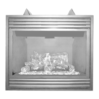
Removing logs and volcanic stone from the firebox.

Typical Installation Sequence

Detailed Installation Steps Overview

Step 1: Framing

Details on framing the appliance opening and clearances.

Fireplace and Framing Specifications

Framing Dimensions

Table of dimensions for various models and vent configurations.

Vent Size Information

Specifies the coaxial DV vent size.

Viewable Glass Size

Dimensions of the viewable glass for different models.

Vertical Venting Through Ceiling

Instructions for framing ceiling openings for vertical vents.

Gas Line Routing and Sizing

Vent Collar Preparation

Vent Collar Preparation (Top Vent)

Steps to prepare the vent collar for top vent usage.

Vent Collar Preparation (Rear Vent)

Steps to prepare the vent collar for rear vent usage.

Step 4: Installing Vent System

Venting System Guidelines

General guidelines for installing the vent system.

Vent Restrictor Installation (Top Vent)

Instructions for installing the vent restrictor for top venting.

Vent Restrictor Installation (Rear Vent)

Instructions for installing the vent restrictor for rear venting.

Vertical Vent Figures and Tables

Vertical (Offset) Installation

Vent Section and Elbow Quantities

Determining vent sections and elbows needed.

Telescopic Vent Section Usage

How to use telescopic vent sections.

Ceiling Opening Framing

Framing ceiling openings for vertical vents.

Attaching Vent Components to Appliance

Connecting vent sections to the appliance collar.

Attaching Vent Components to Each Other

Connecting multiple vent sections together.

Install Firestop/Spacer at Ceiling

Installing firestop/spacers for ceiling penetrations.

Support Vertical Vent Run Sections

Methods for supporting vertical vent pipes.

Changing Vent Direction

Continuing Horizontal/Inclined Vent Installation

Frame Roof Opening

Install Roof Flashing

Install Storm Collar

Install Vertical Termination

Vertical Vent Figures and Tables (Continued)

Vertical Vent Figures and Tables (Continued)

Horizontal Termination System

Plan the Vent Run

Analyze vent routing and determine section quantities.

Frame Exterior Wall Opening

Cutting and framing the opening in the exterior wall.

Frame Ceiling Opening

Framing ceiling openings for horizontal vent runs.

Attach Vent Components to Appliance

Connecting vent components to the appliance collar.

Assemble Vent Run to Exterior Wall

Attach Termination Adapter

Attaching the termination adapter to the vent section.

Install Firestop/Spacer at Exterior Wall

Installing firestop/spacer at the exterior wall opening.

Install the Desired Termination

Installing the square horizontal termination.

Horizontal Vent Figures/Tables

Horizontal Vent Figures/Tables (Continued)

Horizontal Vent Figures/Tables (Continued)

Venting Using Secure Flex Kits

Secure Flex Kit Overview

Using Secure Flex components with rigid vent sections.

Attach Flexible Vent to Adapter

Connecting flexible vent pipe to an adapter.

Route Flex Vent

Routing flexible vent pipe with proper clearances.

Install Firestop/Spacers

Installing firestop/spacers for flex vent penetrations.

Attach Flex Vent to Termination

Connecting flex vent to the termination.

Step 5: Field Wiring

Millivolt Wiring

Wiring diagram for millivolt gas valves and controls.

Electronic Wiring

Wiring diagram for electronic gas valves and controls.

Step 6: Optional Forced Air Blower Kit Wiring

Step 7: Connecting Gas Line

Step 8: Verifying Appliance Operation

Millivolt Appliance Checkout

Checking pilot flame and burner operation for millivolt units.

Electronic Appliance Checkout

Checking pilot flame and operation for electronic units.

Step 9: Install Stone, Embers, and Logs

Volcanic Stone Placement

Instructions for placing decorative volcanic stone.

Glowing Embers Placement

Distributing glowing embers over the burner.

Log Placement Guidelines

Critical steps for proper log placement to prevent sooting.

MPD-3328 Log Placement

MPD-3530 Log Placement

MPD-4035 and MPD-4540 Log Placement

Step 10: Glass Door (Remove/Install)

Removing the Glass Enclosure Panel

Instructions for removing the glass door panel.

Installing the Glass Enclosure Panel

Instructions for reinstalling the glass door panel.

Step 11: Burner Adjustments

Flame Appearance and Sooting

Guidelines for achieving proper flame appearance and avoiding soot.

Air Shutter Adjustment Guidelines

How to adjust air shutters for optimal flame.

Burner Adjustment Warnings and Cautions

Step 12: Hood Installation

Finishing Requirements

Wall Details

Instructions for finishing the wall around the appliance.

Step 13: Attaching Safety Warnings

Attaching Safety-In-Operation Warnings

How to affix safety instruction labels to controls.

Installation Accessories

Listed Secure Vent Components

List of available Secure Vent components.

Installation Accessories Continued

Listed Secure Flex Components

List of available Secure Flex components.

Gas Conversion Kits

Conversion Steps (Millivolt)

Step 4: SIT Systems Conversion

Conversion steps for SIT millivolt systems.

Step 5: Manifold Pressure Test

Testing manifold pressure with a manometer.

Step 6: Pilot Orifice Replacement

Replacing the pilot orifice.

Conversion Steps (Electronic)

Step 7: Honeywell Electronic Valves

Conversion steps for Honeywell electronic valves.

Pilot Orifice Replacement

Step 8: Orifice and Burner Assembly Reassembly

Step 9: Reassemble Components

Step 10: Attach Conversion Label

Step 11: Gas Supply and Leak Test

Related product manuals