Page 15
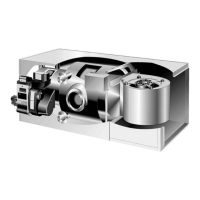
TABLE 7
PRIMARY LIMIT CONTROL (S10)
UNIT
ACTUATES
ON TEMP. RISE
ACTUATES
ON TEMP. FALL
O23Q2−70 210F (99C) 180F (82C)
O23Q3−105/120 220F (104C) 190F (88C)
O23Q5−140/154 210F (99C) 180F (82C)
OHR23Q3−105/120 240F (116C) 210F (99C)
OHR23Q5−140/154 190F (88C) 160F (71C)
OF23Q3−105/120
OF23Q3−105/120R
240F (116C) 210F (99C)
OF23Q5−140/154
OF23Q5−140/154R
210F (99C) 180F (82C)
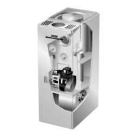
FIGURE 12
INSULATING COVER
LIMIT CONTROL (S10)
SPADE CONNECTORS
LIMIT
D−Blower Compartment (Figure 13)
Blower motor (B3), capacitor (C4), and secondary limit con
trol (S21) are located in the blower compartment. The blow
er compartment can be accessed by removing the blower
access panel.
FIGURE 13
BLOWER COMPARTMENT
(OHR23 SIDE VIEW SHOWN)
BLOWER
MOTOR
CAPACITOR
(C4)
SECONDARY LIMIT
CONTROL (S21)
(OHR23 ONLY)
(BACK SIDE)
BLOWER MOTOR
(B3)
1.Blower Motor (B3) and Capacitor (C4)
All O23, OHR23, and OF23 series units use single phase
direct drive blower motors. All motors used are 115V perma
nent split capacitor motors to ensure maximum efficiency.
See SPECIFICATIONS tables for horsepower and motor
nameplate for capacitor rating.The blower motor is con
nected to the blower control board via the blower motor
plug P43.
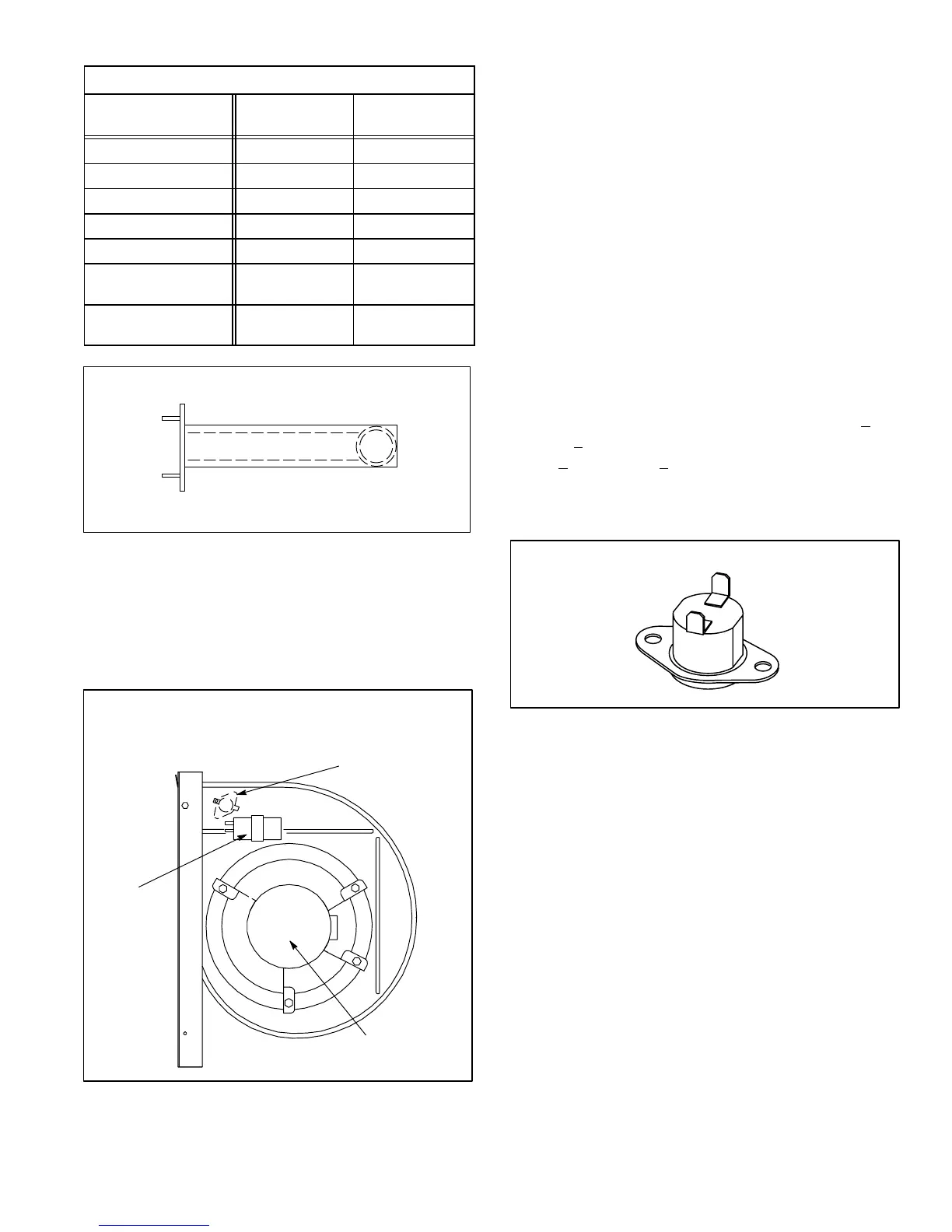
2.Secondary Limit Control (S21)
The secondary limit (S21) is used on the OHR23 series unit
only. The N.C. limit is mounted on the side and toward the
back of the blower housing. See figure 13 for location and fig
ure 14 for type. When excess heat is sensed in the blower
compartment, the limit will open. If the limit is tripped, the blow
er control deenergizes the thermostat, inturn shutting down
the unit. The limit automatically resets when unit tempera
ture returns to normal. The switch opens at 150F + 5F
(65.5C + 2.8C) on a temperature rise and resets at
140F + 5F (60.0C + 2.8C) on a temperature fall. The
switch is factory set and cannot be adjusted. The set
point is printed on the face plate of the limit.
FIGURE 14
SECONDARY LIMIT CONTROL (S21)
E−Optional Accessories
Optional accessories are available from Lennox for the O23,
OHR23, and OF23 series units. Some accessories are in kit
form which come with instructions.
1.Low Speed On − Off Switch (S68)
The low speed on off switch is a kit (catalog # 67H91) which
permits continuous low speed blower operation. The switch is
a DPDT toggle switch.
2.Economizer Relay (K43)
The economizer relay (catalog # 65G40) is used to energize
the economizer if used. The relay is a 120V coil, single pole
contact which is energized by the accessory terminal of the
blower control board.
 Loading...