Page 7
I−UNIT COMPONENTS
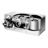
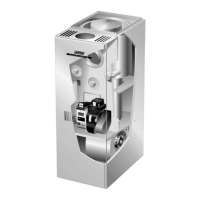
General parts orientation for the O23, OHR23 and OF23 are
shown in figures 1, 2 and 3 respectively. The O23 and OF23
control box, burner, limit switch and cleanout ports may be ac
cessed by removing the front access panel, while the OHR23
components are exposed. The blower can be accessed in the
O23 and OF23 by removing the blower access panel, while in
the OHR23 units two 1/4" screws must be removed before the
blower access panel can be removed.
ELECTROSTATIC DISCHARGE (ESD)
Precautions and Procedures
CAUTION
Electrostatic discharge can affect electronic
components. Take precautions during unit instal
lation and service to protect the unit’s electronic
controls. Precautions will help to avoid control
exposure to electrostatic discharge by putting
the unit, the control and the technician at the
same electrostatic potential. Neutralize electro
static charge by touching hand and all tools on an
unpainted unit surface before performing any
service procedure.
A−Blower Control Board
BCC2 Blower Control Board (Figure 4)
−1 and −2 units
All O23, OHR23 and OF23−1 and −2 oil units utilize the BCC2
(A15) blower control manufactured by Heatcraft. The BCC2 is
a printed circuit board which controls the supply air blower and
monitors the limit controls and oil burner operation. The control
has a nonadjustable, factory preset fanon" timing. Fan off"
timing is adjustable. The board is divided into two sec
tions, 120 and 24VAC. Line voltage comes into the board
on the 120VAC side. See figure 4. See table 1 for BCC2
terminal designations.
DANGER
Shock hazard. Avoid personal injury. Make sure to
disconnect power before changing fan off" timing.
Blower Operation and Timing
Blower off" timing (time that the blower operates after the heat
demand has been satisfied) is determined by the arrange
ment of a jumper across pins on the BCC2 blower control
board. See figure 4. To adjust fan off " timing, gently discon
nect jumper and reposition across pins corresponding with
new timing. Fan on" time is factory set at 45 seconds and is
not adjustable.
NOTEIf fan off" time is set too low, residual heat in
heat exchanger may cause primary limit S10 or auxilary
limit S21 to trip resulting in frequent cycling of blower. If
this occurs, adjust blower to longer time setting.
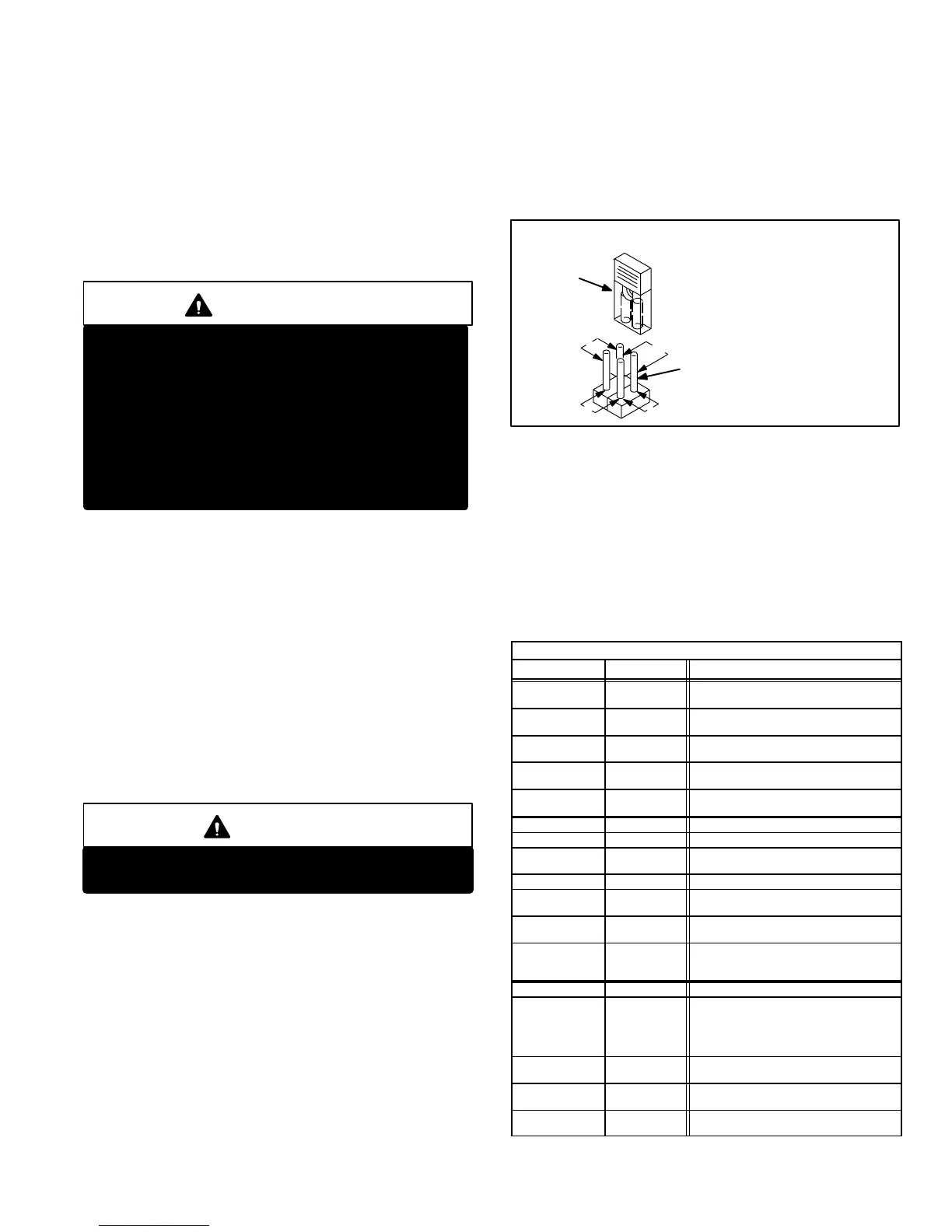
Figure 5 shows the various fan off" timings and how
jumper should be positioned. Unit is shipped with a fac
tory fan off" setting of 150 seconds. Fan off" time will
affect comfort and efficiency and is adjustable to satisfy
individual applications. The fan off" timing is initiated
after a heating demand but not after a blower or cooling
demand (that is, when indoor thermostat switch is
changed from ON to AUTO and heating/cooling demand
is not present, the blower stops immediately).
FIGURE 5
FANOFF TIME ADJUSTMENT
270
210
150 90
To adjust fan−off timings:
Remove jumper from BCC2
and select one of the other pin com
binations to achieve the
desired time.
TIMING
JUMPER
TIMING PINS (seconds)
Leave jumper off to achieve
330 second fan−off timing.
Fanoff timing is factory
set at 150 seconds
Thermostat Connection
Thermostat wires are connected to terminal strip TB1 found
on the BCC2 control board. The terminal strip is clearly
marked with the corresponding thermostat designation.
The terminal strip (jack / plug 94) is simply removed by
grasping the ends of the block and rotating down while pull
ing away (see figure 4).
TABLE 1
BLOWER CONTROL A15 TERMINAL DESIGNATIONS
Terminal Type Function
W
Detachable
Screw Strip
Heating Demand
R
Detachable
Screw Strip
24VAC to Thermostat
Y
Detachable
Screw Strip
Cooling Demand
C
Detachable
Screw Strip
24VAC Common
To Indoor Thermostat
G
Detachable
Screw Strip
Blower Demand
NEUTRAL 1/4" Spade 120VAC Neutral
L1 1/4" Spade 120VAC Line Voltage In
A 1/4" Spade
Switched 120VAC
to Blower Cooling Tap
XFMRN 1/4" Spade 120VAC Transformer Common
CF 1/4" Spade
Switched 120VAC to
Continuous Blower Tap
H 1/4" Spade
Switched 120VAC to
Blower Heating Tap
ACC 1/4" Spade
Switched 120VAC to Accessory
(Electronic Air Cleaner,
Humidifier, Etc. 1 amp rating.)
VALVE SENSE 3/16" Spade 24VAC Output To Burner
LIMIT 1/4" Spade
24VAC In From Primary Limit.
Limit Open: Stops Burner and Turns
On Blower
Limit Closed: Allows Burner
Operation
WI 1/4" Spade
24VAC Thermostat
Demand Output
24V 1/4" Spade
24VAC Input
From Transformer
COM 1/4" Spade
24VAC Common
From Transformer
 Loading...