Page 21
3− Insofar as is practical, close all building doors and
windows and all doors between the space in which
the appliances remaining connected to the com
mon venting system are located and other spaces of
the building. Turn on clothes dryers and any ap
pliances not connected to the common venting sys
tem. Turn on any exhaust fans, such as range hoods
and bathroom exhausts, so they will operate at maxi
mum speed. Do not operate a summer exhaust fan.
Close fireplace dampers.
4− Following the lighting instruction on the unit, place the
appliance being inspected in operation. Adjust thermo
stat so appliance will operate continuously.
5− Test for spillage using a draft gauge.
6− After it has been determined that each appliance re
maining connected to the common venting system
properly vents when tested as outlined above, return
doors, windows, exhaust fans, fireplace dampers and
any other fuel burning appliance to their previous condi
tion of use.
7− If improper venting is observed during any of the
above tests, the common venting system must be
corrected.
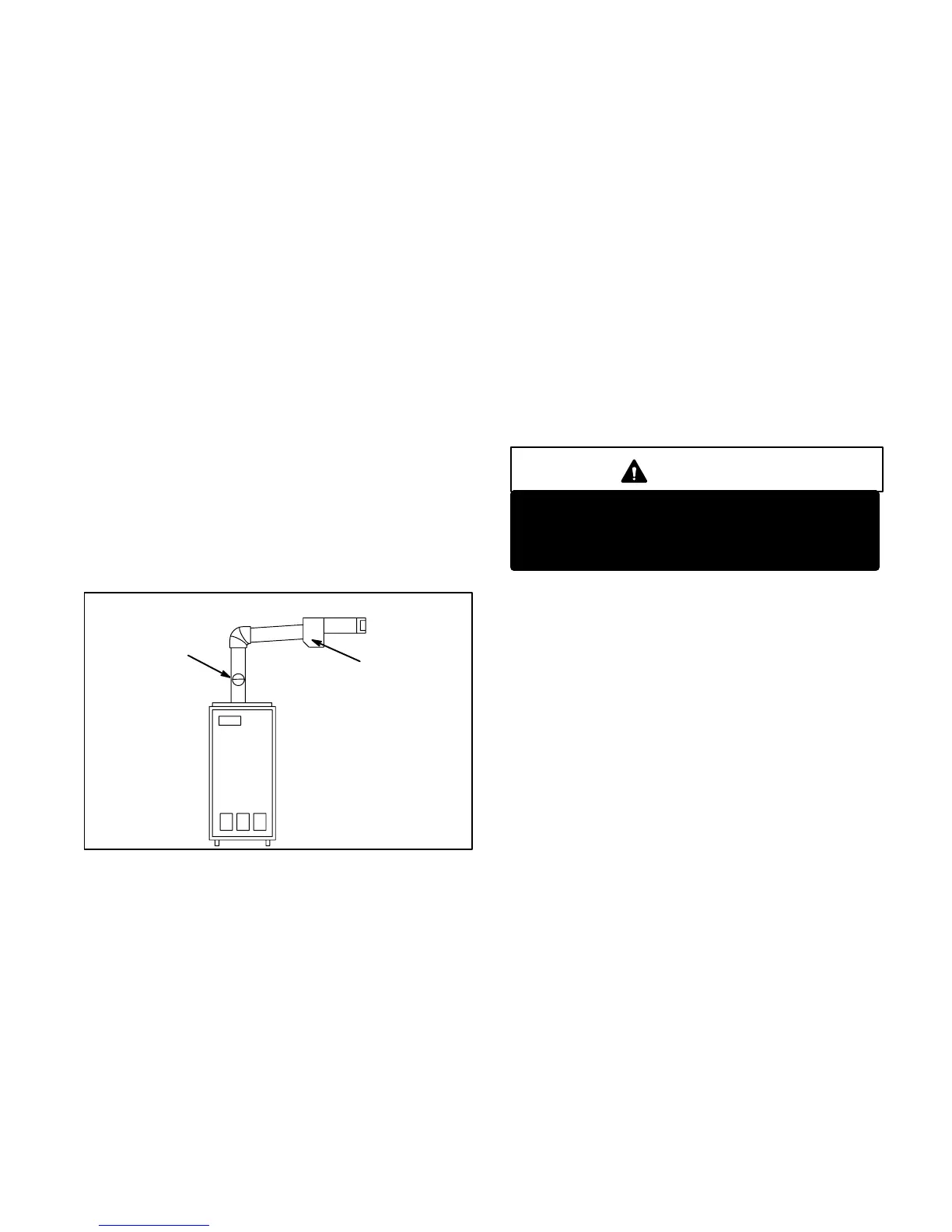
Horizontal Venting
HORIZONTAL VENTING
BAROMETRIC
CONTROL*
CONTROL FOR
HORIZONTAL
VENTING
FIGURE 24
*When using indoor air,
barometric control must be
installed in the horizontal
venting system and located
within 18" (457 mm) of vent
outlet of furnace.
When using direct connection,
barometric control must be
installed in the intake air pipe.
The O23 is approved for horizontal venting with the fol
lowing mechanical vent systems:
Tjernlund (sideshot) #SS1C and Field Controls #SWG−5 with
the CK−61 control kit. Refer to manufacturers’ installation
instructions for proper installation procedures and service
parts information.
Do not common vent with any other appliance when using
sidewall vent system.
Maximum permissible vent length is 70 equivalent feet (21.3
m). Minimum length is 15 equivalent feet (4.6 m). Each 90
elbow is equal to 6 feet (1.8 m) of straight pipe, each 45 el
bow is equal to 3 feet (0.9 m) of straight pipe. Minimum vent
pipe diameter is 4" (102 mm). Vent pipe of 5" (127 mm) and 6"
(152 mm) is permissible. Calculate the equivalent vent pipe
footage from the furnace to the mechanical vent system
(Tjernlund or Field Controls) by adding the straight vent pipe
length and the equivalent elbow lengths together.
The barometric draft control must be used in horizontal (side
wall) venting system. It must be located within 18" (457 mm) of
the furnace vent outlet. See figure 24 for barometric draft con
trol location.
III−STARTUP
A−Preliminary and Seasonal Checks
1− Inspect electrical wiring, both field and factory installed
for loose connections. Tighten as required.
2− Check line voltage. Voltage must be within range
listed on the nameplate. If not, consult the power
company and have voltage condition corrected be
fore starting unit.
B−Heating StartUp
FOR YOUR SAFETY READ BEFORE LIGHTING
WARNING
Do not attempt to start the burner when excess
oil has accumulated in the chamber, when the
furnace is full of vapor or when the combus
tion chamber is very hot.
1− Set thermostat for heating demand.
2− Turn on electrical supply to unit and open all shutoff
valves in the oil supply line to the burner..
3− Check air adjustment dial on the right side of the burn
er (see figure 9). Set according to table 4.
4− On single line applications the oil pump must be
primed by bleeding the oil line. Open air bleed port and
start burner. A hose may be attached to direct oil into a
container. After last bubble is seen, bleed pump for 15
seconds. Hurried bleeding will impair efficient unit op
eration. Close port to stop bleeding. Single line instal
lations must be absolutely air tight to prevent leaks or
loss of prime.
5− If burner stops after flame is established, repeat the
bleeding procedure.
NOTE−Air bleeding is automatic on two line applica
tions; however, opening air bleed port will allow a faster
bleed. Run return line back to tank and terminate three to
four inches above the inlet line. Failure to bleed the sys
tem may cause air to be introduced into the system result
ing in a loss of prime.
6− If the burner does not start immediately, check the
safety switch on the burner primary control.
7− If burner fails to light again, refer to the trouble
shooting section in the back of this manual.
8− Proceed to section IV to complete start up.
C−Safety or Emergency Shutdown
Turn off unit power. Close all shutoff valves in the oil sup
ply line.
 Loading...