Page 23
er for a short period and then turn off. The gauge shows
cutoff pressure.
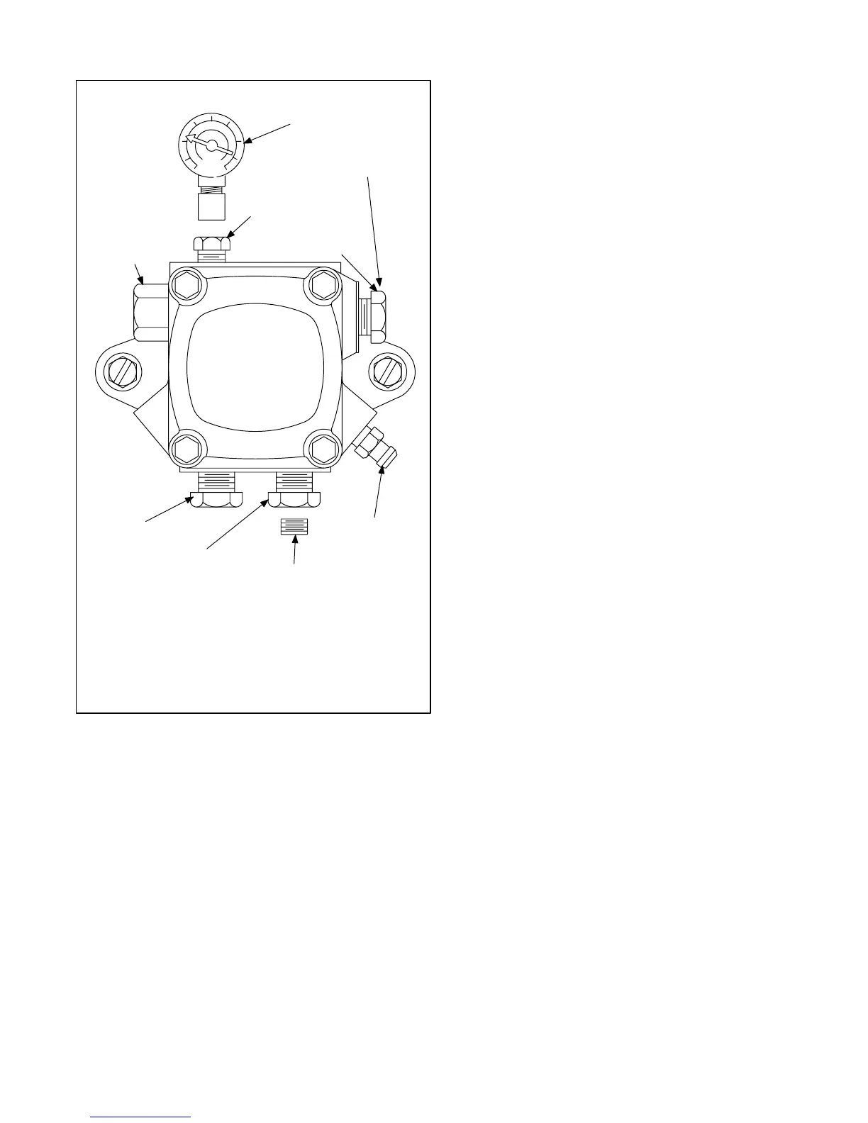
PRESSURE
GAUGE
PORT (1/8" [3mm])
INLET PORT
(1/4" [6mm])
FIGURE 28
OIL PUMP PRESSURE CHECK
RETURN PORT
(1/4" [6mm])
**TO ADJUST PRESSURE: INSERT STANDARD SCREWDRIVER.
TURN COUNTERCLOCKWISE BELOW DESIRED PRESSURE,
THEN TURN CLOCKWISE TO SET DESIRED PRESSURE.
NOZZLE PORT
(1/8" [3mm])
*PRESSURE CHECKS: NORMAL OPERATING PRESSURE IS
100 PSIG (689.5 kPa) FOR THE 023Q270 AND 140 PSIG (965.3 kPa)
FOR ALL OTHER O23, OHR23, AND OF23 UNITS. NOZZLE CUTOFF
PRESSURE IS APPROXIMATELY 80 PSIG (551.6 kPa).
BLEED PORT
1/16" (2mm) BYPASS PLUG
INSERT FOR TWOPIPE SYSTEM
(use 5/32" [4mm] allen wrench)
INLET PORT
SHOWN (1/4" [6mm])
**REGULATE PRESSURE
NOT SHOWN
(beside the inlet port)
*PRESSURE GAUGE
D−Burner Adjustment
The following instructions are essential to the proper opera
tion of O23 series oil furnaces. To prevent sooting, these in
structions must be followed in sequence:
NOTE−All w.c. measurements are below atmospheric
pressure (negative readings).
1−Draft
This test should be taken at the vent connector between
the breaching and the barometric damper. Generally a 1/4"
(6 mm) hole will need to be drilled for the draft gauge to be
inserted into the vent connector.
A minimum of 0.03" w.c. (7.5 Pa) draft must be estab
lished without the burner in operation. With the burner in
operation, the draft should be 0.04" w.c. (9.9 Pa) to 0.05"
w.c. (12.4 Pa). This is VERY critical to the flame retention
head burners.
Oil furnace installations also require careful inspection to
make sure the chimney is in good condition and can ac
commodate the products of combustion. The temperature
in unconditioned space will also affect the draft if long vent
connectors are allowed to get too cold.
2−Overfire Draft
This test should be taken with the burner in operation.
Remove the screw from the center of the center inspec
tion port. Insert your draft gauge into the hole.
A reading of the overfire draft should be 0.02" w.c. (5.0 Pa)
less than the reading found in the vent connector. If a posi
tive reading is seen at this point, the secondary heat ex
changer may be sooted or to much air may be entering
into the heat exchanger from the combustion fan. Adjust
ments to the combustion fan can be made using the air
adjustment dial.
3−Smoke Test
The smoke test should be taken at hole drilled in step 1.
Using a smoke test gun adjust the air inlet shutter so that
you will have just a trace of smoke. Somewhere be
tween a 0 and #1 smoke. This is the starting point. Do
not stop here. After the smoke test take a CO sample.
C.S.A. requires no more than 400ppm. However, a
properly installed unit under normal operating condi
tions should not read more than 50ppm.
4−CO
2
Test
Again to be taken at the vent connector pipe. With the
unit firing at a trace of smoke, test for percentage of CO
2
in the vent gas.
From the results of this test, a window of operation" will be
determined. This window of operation establishes some tol
erance. The tolerance the installer builds in provides room
within the setup for those things which might affect com
bustion. Those things which might affect combustion can
then do so without causing the unit to start sooting/smoking.
Things which might affect combustion include a nozzle go
ing bad, draft that changes during different climatic condi
tions, dirty oil, dirt obstructing the air inlet, etc.
To build in a window of operation," set up the burner to be
2% less in CO
2
. For example, if you find a reading of 12%
CO
2
, adjust the air inlet shutter to increase the air and drop
the CO
2
to 10%.
5−Retest the Smoke
With a drop in the CO
2
and increase in the air you should
see that the smoke has returned to 0.
6−Retest the Overfire Draft
This test serves to confirm that you have not increased the air
too much. Again you do not want a positive pressure at the
test port. It should still be 0.02" w.c. (5.0 kPa) less than the
draft from the vent connector. You may need to increase the
stack draft by adjusting the barometric damper.
 Loading...