EasyManua.ls Logo

Lennox SGH036 User Manual

Lennox SGH036
60 pages
To Next Page IconTo Next Page
Page #1 background imageLoading...
Page #1 background image
©2019
SGH120 SHOWN
IMPORTANT
Supply air VFD motor rotation is controlled indepen
dently from scroll compressor rotation. See Cooling
Start-Up section for correct compressor rotation.
Compressor damage due to improper rotation is the
responsibility of the installer.
Table of Contents
Dimensions Page 2.................................
Parts Arrangements Page 5.........................
Shipping and Packing List Page 8....................
General Page 8....................................
Safety Page 8.....................................
Unit Support Page 9................................
Duct Connection Page 10............................
Rigging Unit For Lifting Page 10.......................
Condensate Drains Page 10..........................
Gas Piping Page 11.................................
Pressure Test Gas Piping Page 11.....................
RETAIN THESE INSTRUCTIONS FOR FUTURE REFERENCE
INSTALLATION
INSTRUCTIONS
SGH/SCH036 (3 TON)
SGH/SCH060 (5 TON)
SGH/SCH120 (10 TON)
SGH/SCH240 (20 TON)
ROOFTOP UNITS
507964-01
9/2019
Supersedes 507364-02
High Altitude Derate Page 12.........................
Optional Outdoor Air Hood Page 13....................
Electrical Connections Page 15.......................
Blower Operation and Adjustments Page 17............
Cooling Start-Up Page 29............................
Cooling Operation and Adjustments Page 31............
Gas Heat Start-Up Page 41...........................
Electric Heat Start-Up Page 43........................
Heating Operation and Adjustments Page 43............
MSAV
t Unit Start-Up Page 45........................
MSAV
t Operation Page 46..........................
Direct Drive Start-Up Page 47.........................
Hot Gas Reheat Startup Page 49......................
Economizer Start-Up Page 53.........................
Service Page 55....................................
Factory Control Parameter Settings Page 58............
Start-Up Report Page 60.............................
WARNING
Improper installation, adjustment, alteration, service
or maintenance can cause property damage, person
al injury or loss of life. Installation and service must
be performed by a licensed professional HVAC in
staller or equivalent, service agency, or the gas sup
plier
WHAT TO DO IF YOU SMELL GAS:
If the information in this manual is not
followed exactly, a fire or explosion
may result causing property damage,
personal injury or loss of life.
WARNING
Do not store or use gasoline or
other flammable vapors and liq
uids in the vicinity of this or any
other appliance.
Installation and service must be
performed by a qualified installer,
service agency or the gas supplier.
S Do not try to light any appliance.
S Extinguish any open flame.
S Do not touch any electrical switch; do not
use any phone in your building.
S Immediately call your gas supplier from a
neighbor's phone. Follow the gas suppli
er's instructions.
S If you cannot reach your gas supplier, call
the fire department.
S Leave the building immediately.
Question and Answer IconNeed help?

Do you have a question about the Lennox SGH036 and is the answer not in the manual?

Lennox SGH036 Specifications

General IconGeneral
Cooling Capacity (BTU/h)36, 000
Sound Level (dB)74
RefrigerantR-410A
Operating Voltage208/230V
Phase1
Sound Level (Outdoor Unit)74
SEER16

Summary

Unit Dimensions

SG/SC 036 & 060 Dimensions

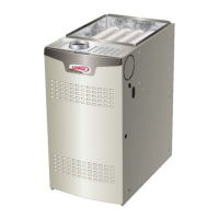
Provides physical dimensions and layout for SG/SC 036 and 060 models.

SG/SC 120 Dimensions

Shows physical dimensions and layout for SG/SC 120 models.

SG/SC 240 Dimensions

Details physical dimensions and layout for SG/SC 240 models.

Parts Arrangement

SG 036 & 060 Parts Arrangement

Illustrates the location of major components for SG 036 & 060 units.

SG 120 Parts Arrangement

Identifies key parts for the SG 120 model.

SG 240 Parts Arrangement

Depicts the arrangement of parts for the SG 240 unit.

Installation and Safety Guidelines

Shipping and Packing List

Lists items included in the unit's packaging and shipping.

General Installation Guidance

Provides general installation guidance and regulatory information.

Safety Precautions

Outlines critical safety precautions for installation and operation.

Recommended Service Clearances

Specifies required clearances around the unit for safe operation and service.

Unit Support, Rigging, and Connections

Unit Support - Downflow Discharge Applications

Details requirements for supporting the unit on a roof or frame.

Rigging Instructions

Provides instructions and precautions for safely lifting and rigging the unit.

Duct Connections

Specifies requirements for connecting ductwork to the unit.

Gas Piping and High Altitude Adjustments

Connect Gas Piping - SG Units

Outlines procedures and considerations for connecting the gas supply piping to SG units.

Pressure Test Gas Piping - SG Units

Details the process for pressure testing the gas piping system for safety.

High Altitude Derate

Explains how to adjust unit performance for high altitude installations.

Electrical Connections

POWER SUPPLY

Covers the main electrical power connections and safety.

CONTROL WIRING

Explains how to wire controls, thermostats, and sensors.

Thermostat and Sensor Wiring

Wiring diagrams for connecting various thermostat and sensor types to the unit.

Blower Operation and Adjustments

Blower Access and Service

Details how to access and service belt drive and direct drive blower assemblies.

Determining Unit CFM

Method for calculating unit airflow (CFM) under wet coil conditions.

Belt Tension Adjustment

Instructions on how to adjust belt tension for optimal performance and life.

Cooling Start-Up and Operation

Cooling Start-Up Procedures

Provides steps and precautions for initiating cooling operation.

Compressor Voltage Phasing

Critical information on ensuring correct phase rotation for compressors.

Refrigerant Charge and Check

Guides on checking and adjusting refrigerant charge for optimal cooling.

Charging Curves

Graphical data to assist in verifying and adjusting refrigerant charge.

Heating Operation

Gas Heat Start-Up

Outlines the procedure for safely starting the gas heating system.

Electric Heat Start-Up

Details the start-up sequence for units equipped with electric heat.

Heating Sequence of Operation

Describes the operational sequence for the heating cycle.

Gas Manifold Pressure Adjustment

How to adjust gas manifold pressure for optimal heating performance.

Advanced Blower Operation

MSAV™ Unit Start-Up

Procedures for starting up units equipped with MSAV™ (VFD) blowers.

Direct Drive Blower Start-Up

Procedures for starting up direct drive blowers.

Set Minimum Damper Position

Setting minimum damper positions for ventilation air volumes.

Reheat and Economizer Systems

Hot Gas Reheat Operation

Procedures for starting up and operating the hot gas reheat dehumidification mode.

Check-Out Procedures

Procedures for verifying proper operation after installation and setup.

Optional Economizer Settings

Configuration options and settings for the economizer system.

Economizer Operation Modes

Explains economizer operation modes based on thermostat and system status.

Service and Maintenance

General Service Guidelines

General maintenance and service recommendations for the unit.

Filter Maintenance

Guidance on filter selection, checking, and replacement.

Burner and Inducer Maintenance

Instructions for inspecting and cleaning burners and the combustion air inducer.

Factory Unit Controller Settings

Information on adjusting unit controller settings using tables.

START-UP REPORT

Inspections and Checks

Section for recording results of initial inspections and checks.

Cooling and Heating Checks

Fields to record data during cooling and heating system start-up.

Accessory Checks

Section to document checks on installed accessories like economizers.

Related product manuals