Page 43
A-Heat Exchanger and Burners
Cleaning the Heat Exchanger and Burners
NOTE - Use papers or protective covering in front of the
furnace during cleaning.
1 - Turn o both electrical and gas power supplies to
furnace.
2 - Remove ue pipe, top cap, ue chase and internal
ue pipe assembly from the unit.
3 - Label the wires from gas valve, rollout switches,
primary limit switch and make-up box then
disconnect them.
4 - Remove the screws that secure the combustion air
inducer pressure switch assembly to the collector
box. Carefully remove the combustion air inducer
to avoid damaging blower gasket. If gasket is
damaged, it must be replaced to prevent leakage.
5 - Remove the collector box located behind the
combustion air inducer. Be careful with the collector
box gasket. If the gasket is damaged, it must be
replaced to prevent leakage.
6 - Disconnect gas supply piping. Remove the screw
securing the burner box cover and remove cover.
Remove the four screws securing the burner
manifold assembly to the vestibule panel and
remove the assembly from the unit.
7 - Remove screws securing burner box and remove
burner box.
8 - Remove screws from both sides, top and bottom of
vestibule panel.
9 - Remove heat exchanger. It may be necessary
to spread cabinet side to allow more room. If so,
remove ve screws from the left side or right side of
cabinet. See FIGURE 22.
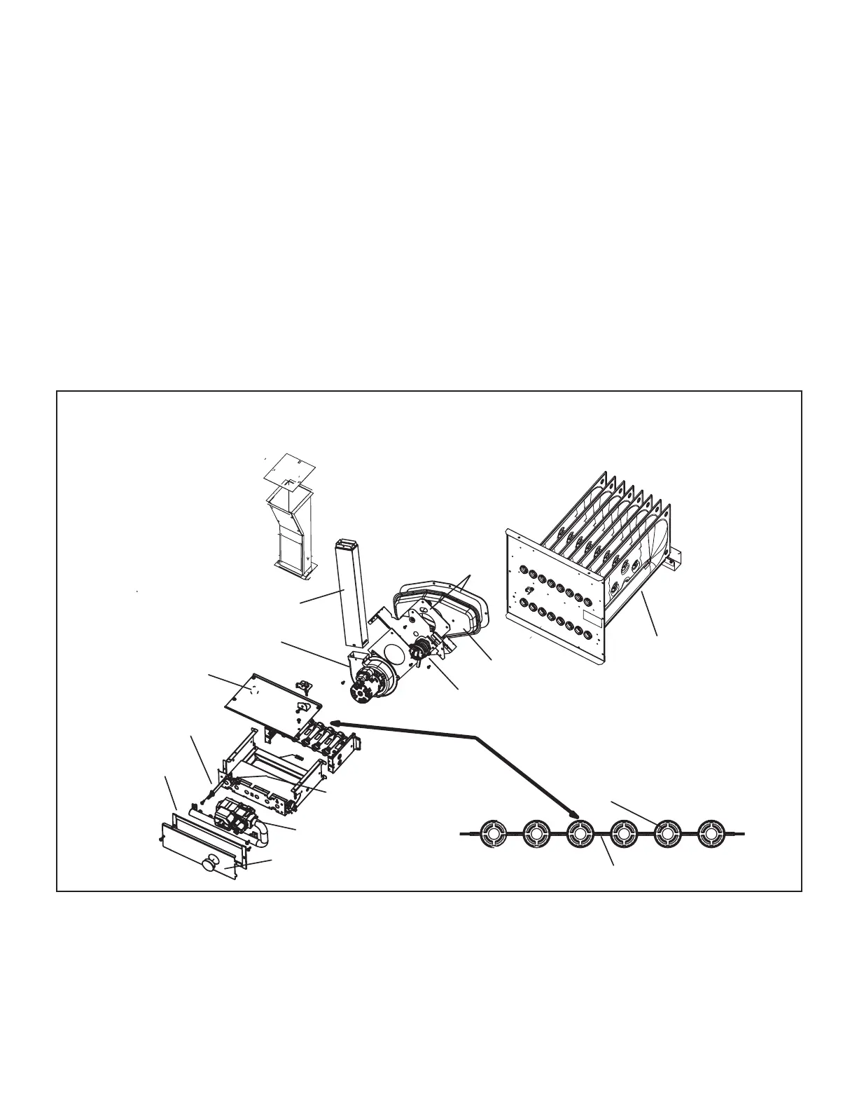
BURNER, C.A.I ASSEMBLY &
HEAT EXCHANGER REMOVAL
heat exchanger
gasket
collector box
orifice plate
internal flue pipe
pressure switch
combustion air inducer
burner box cover plate
manifold and gas valve
gasket
retention rings
cross over
gasket
rollout switch
sensor
rollout switch
(alternate location)
Sight glass
FIGURE 21

 Loading...


