Page 14
TABLE 9
Low Heat Blower Speeds
Thermostat
Demand
Blower
Speed
Adjust
ments
DIP SWITCH SETTINGS
14 15 16
Low Heat
(R to W1)
+15% On Off On
+7.5% On Off Off
Normal Off Off Off
-7.5% On On Off
-15% On On On
Switches 14 through19 -- Heating Mode Blower Speed
-- Switches 14 through 19 are used to select heating mode
blower motor speeds. These switches are factory set at the
OFF position which provides 100 % of normal speed during
HIGH HEAT demand, 70% of normal speed during MID-
RANGE HEAT demand and 35% of normal speed during
LOW HEAT demand. Switches 14, 15 and 16 are used to
adjust the LOW FIRE blower motor speed. Switches 17, 18
and 19 are used to adjust the HIGH FIRE blower motor
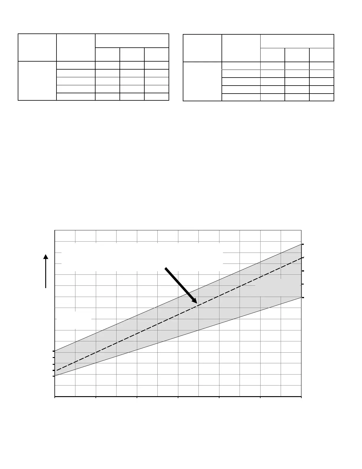
speed. Figure 6 and tables 9 and 10 provides the heating
mode blower speeds that will result from different switch
settings. Figure 6 indicates the effect the DIP switch set
tings (tables 20 &21 above) have upon the heating airflow at
various furnace firing rates.
Refer to blower tables at the front of this manual for corre
sponding cfm values.
TABLE 10
High Heat Blower Speeds
Thermostat
Demand
Blower
Speed
Adjust
ments
DIP SWITCH SETTINGS
17 18 19
High Heat
(R to
W1 & W2)
+15% On Off On
+7.5% On Off Off
Normal
Off Off Off
-7.5% On On Off
-15% On On On
Low Fire
Dip Switches
14, 15, 16
High Fire
Dip Switches
17, 18, 19
Airflow Determination
S Identify blower speed adjustment points at low and high fire
S Airflow will lie on straight line between these two points and will fall within
the shaded area as shown
EXAMPLE -7.5% at low fire +7.5% at high fire
35%
50%
60%
70%
80%
90%
100%
RATE (%)
+15%
+7.5%
-7.5%
-15%
Nominal
-15%
Nominal
-7.5%
+7.5%
+15%
Increasing
Airflow
FIGURE 6
 Loading...


