Page 31
After calibration, the integrated control stores the RPM1
and RPM2 values. The low fire (35%) and high fire (100%)
RPM points are calculated by adding margin values to the
RPM1 and RPM2 values.
The integrated control also initiates a low fire switch check
at the end of a normal heating cycle described below. If this
check fails the pressure switch calibration will follow on the
next call for heat.
1- The inducer runs 15 seconds at the last firing rate
before the heat call ended.
2- Inducer runs at 35% firing rate RPM (RPM1 + low
pressure switch open RPM margin value).
3- If low pressure switch is open, set flag for calibration
on next call for heat. Turn inducer off until next call for
heat.
4- If low pressure switch is closed move inducer speed
to RPM1. Allow 5 seconds for stabilization.
5- If low pressure switch opens turn off inducer. No fur
ther action.
6- If low pressure switch is still closed, decrease induc
er speed 1/2 of the low pressure switch open RPM mar
gin. Allow 5 seconds to stabilize.
7- If low pressure switch is open turn off inducer. No fur
ther action.
8- If low pressure switch is still closed, set flag for cal
ibration on next call for heat and turn off inducer.
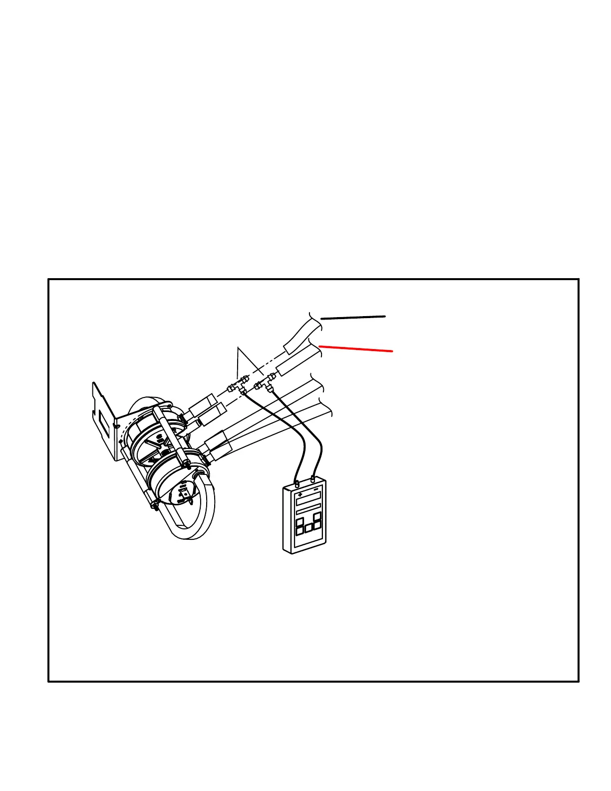
Measuring pressure differential (Figure 18)
Checks of pressure differential can aid in troubleshooting. Len
nox provides a kit (10L34) if necessary. When measuring the
pressure differential, readings should be taken at the pressure
switch. Lack of differential usually indicates problems in the in
take or exhaust piping, but may indicate problems in the
heat exchanger, condensing coil, header boxes, com
bustion inducer or other components.
The differential pressure is the difference in pressure mea
sured across the cold end header box orifice.
FIGURE 18
1 - Remove thermostat demand and allow unit to cycle off.
2 - Install a tee in the negative (-) line (red and black tubing or red
tubing) and a tee in the positive (+) line (black tubing) running
from the pressure switch to the cold end header box.
3 - Install a measuring device with hose from the negative (-)
side of the measuring device to the tee installed in the neg
ative (-) line and with hose from the positive (+) side of the
measuring device to the tee in the positive (+) line.
NOTE - Both sides of the cold end header box are negative.
However the (+) port reads less negative pressure than the (-)
port.
4 - Operate unit and observe measuring device reading.
Readings will change as heat exchanger warms.
a. Take one reading immediately after start‐up.
b. Take a second reading after unit has reached steady
state (approximately 5 minutes). This will be the pressure
differential.
The pressure differential should be greater
than those listed in table 20.
5 - Remove thermostat demand and allow to cycle off.
6 - Remove measuring device and tee's. Reinstall combustion
air sensing hoses to the pressure switch.
RED and BLACK TUBING
or RED TUBING NEGATIVE
BLACK TUBING
POSITIVE
Measuring Pressure Differential
To Cold End Header Box
Field Installed
Measuring Device
Red
 Loading...


