Page 38
Venting Practices
FIGURE 22
* See table 21 for allowable pipe.
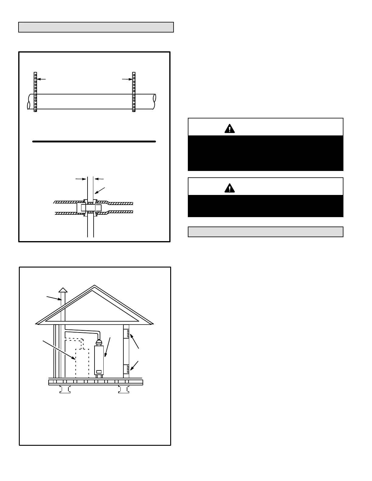
Piping Suspension Guidelines
NOTE - Isolate piping at the point where it exits the outside wall or
roof in order to prevent transmission of vibration to the structure.
SCHEDULE 40 PVC --
Support every 5 feet.
all other pipe* --
Support every 3 feet.
Wall
inside outside
24” maximum
3/4” minimum
Wall Thickness Guidelines
REPLACING FURNACE THAT WAS PART OF A
COMMON VENT SYSTEM
CHIMNEY
OR GAS
VENT
(Check sizing
for water
heater only)
FURNACE
(Replaced
by SLP98)
WATER
HEATER
OPENINGS
(To Adjacent
Room)
If an SLP98 furnace replaces a furnace which was com
monly vented with another gas appliance, the size of the
existing vent pipe for that gas appliance must be checked.
Without the heat of the original furnace flue products, the
existing vent pipe is probably oversized for the single water
heater or other appliance. The vent should be checked for
proper draw with the remaining appliance.
FIGURE 23
1. In areas where piping penetrates joists or interior walls,
hole must be large enough to allow clearance on all
sides of pipe through center of hole using a hanger.
2. When furnace is installed in a residence where unit is
shut down for an extended period of time, such as a
vacation home, make provisions for draining condensate
collection trap and lines.
Exhaust Piping (Figure 25)
Route piping to outside of structure. Continue with installa
tion following instructions given in piping termination sec
tion.
CAUTION
Do not discharge exhaust into an existing stack or
stack that also serves another gas appliance. If verti
cal discharge through an existing unused stack is re
quired, insert PVC pipe inside the stack until the end
is even with the top or outlet end of the metal stack.
CAUTION
The exhaust vent pipe operates under positive pres
sure and must be completely sealed to prevent leak
age of combustion products into the living space.
Vent Piping Guidelines
NOTE - Lennox has approved the use of DuraVent
®
and
Centrotherm manufactured vent pipe and terminations as
an option to PVC. When using the PolyPro
®
by DuraVent or
InnoFlue
®
by Centrotherm venting system the vent pipe re
quirements stated in the unit installation instruction – minim
um & maximum vent lengths, termination clearances, etc. –
apply and must be followed. Follow the instructions
provided with PoyPro by DuraVent and InnoFlue
®
by Cen
trotherm venting system for assembly or if requirements are
more restrictive. The PolyPro by Duravent and InnoFlue by
Centrotherm venting system must also follow the uninsu
lated and unconditioned space criteria listed in table 26.
The SLP98DFV is installed only as a Direct Vent gas cen
tral furnace.
NOTE - In Direct Vent installations, combustion air is taken
from outdoors and flue gases are discharged outdoors.
Intake and exhaust pipe sizing -- Size pipe according to
tables 23 and 24. Count all elbows inside and outside the
home. Table 23 lists the minimum vent pipe lengths per
mitted. Table 24 lists the maximum pipe lengths permitted.
Regardless of the diameter of pipe used, the standard roof
and wall terminations described in section Exhaust Piping
Terminations should be used. Exhaust vent termination
pipe is sized to optimize the velocity of the exhaust gas as it
exits the termination. Refer to table 27.
In some applications which permit the use of several differ
ent sizes of vent pipe, a combination vent pipe may be used.
Contact Lennox' Application Department for assistance in
sizing vent pipe in these applications.
 Loading...


