Page 44
General Guidelines for Vent Terminations
In Direct Vent applications, combustion air is taken from
outdoors and the flue gases are discharged to the out
doors. The SLP98DFV is classified as a direct vent, Cate
gory IV gas furnace.
In Direct Vent applications, the vent termination is limited
by local building codes. In the absence of local codes, refer
to the current National Fuel Gas Code ANSI Z223-1/NFPA
54 in U.S.A., and current CSA-B149 Natural Gas and Pro
pane Installation Codes in Canada for details.
Position termination according to location given in figure 27.
In addition, position termination so it is free from any ob
structions and 12” above the average snow accumulation.
At vent termination, care must be taken to maintain
protective coatings over building materials (prolonged
exposure to exhaust condensate can destroy protective
coatings). It is recommended that the exhaust outlet not be
located within 6 feet (1.8m) of a condensing unit because
the condensate can damage the painted coating.
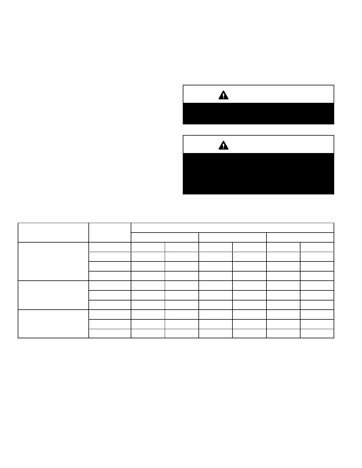
NOTE - See table 26 for maximum allowed exhaust pipe
length without insulation in unconditioned space during
winter design temperatures below 32°F (0°C). If required
exhaust pipe should be insulated with 1/2” (13mm) Arma
flex or equivalent. In extreme cold climate areas, 3/4”
(19mm) Armaflex or equivalent may be necessary. Insula
tion must be protected from deterioration. Armaflex with
UV protection is permissable. Basements or other en
closed areas that are not exposed to the outdoor ambient
temperature and are above 32 degrees F (0°C) are to be
considered conditioned spaces.
IMPORTANT
Do not use screens or perforated metal in exhaust ter
minations. Doing so will cause freeze-ups and may
block the terminations.
IMPORTANT
For Canadian Installations Only:
In accordance to CSA International B149 installation
codes, the minimum allowed distance between the
combustion air intake inlet and the exhaust outlet of
other appliances shall not be less than 12 inches
(305mm).
TABLE 26
Maximum Allowable Vent Pipe Length (in ft.) Without Insulation In Unconditioned Space For
Winter Design Temperatures Modulating High Efficiency Furnace
Winter Design
Temperatures
1
°F (°C)
Vent Pipe
Diameter
Unit Input Size
070 090 110
32 to 21
(0 to -6)
PVC
2
PP PVC
2
PP PVC
2
PP
2 in. 11 9 14 12 18 15
2-1/2 in. 7 N/A 10 N/A 12 N/A
3 in. N/A N/A 6 6 8 8
20 to 1
(-7 to -17)
2 in N/A N/A 6 4 8 6
2-1/2 in. N/A N/A N/A N/A N/A N/A
3 in. N/A N/A N/A N/A N/A N/A
0 to -20
(-18 to -29)
2 in. N/A N/A N/A N/A N/A N/A
2-1/2 in. N/A N/A N/A N/A N/A N/A
3 in. N/A N/A N/A N/A N/A N/A
1
Refer to 99% Minimum Design Temperature table provided in the current edition of the ASHRAE Fundamentals Handbook.
2
Poly-Propylene vent pipe (PP) by Duravent and Centrotherm.
NOTE - Concentric terminations are the equivalent of 5' and should be considered when measuring pipe length.
NOTE - Maximum uninsulated vent lengths listed may include the termination(vent pipe exterior to the structure) and cannot exceed 5 linear feet or the
maximum allowable intake or exhaust vent length listed in table 24 which ever is less.
NOTE - If insulation is required in an unconditioned space, it must be located on the pipe closest to the furnace. See figure28.
 Loading...


