EasyManua.ls Logo

Lennox Value Series - User Manual

Lennox Value Series
12 pages
Print Icon
To Next Page IconTo Next Page
Loading...
3DJH
£
PRODUCT LITERATURE
¤
1998 Lennox Industries Inc.
Dallas, Texas
VALUE 10
TM
CONDENSING UNIT
Value 10 condensing units are designed for expansion
valve (TXV) and RFC systems. Refer to Lennox engi-
neering handbook for expansion valve kits which must
be ordered separately.
SHIPPING AND PACKING LIST
1-- Assembled 10ACB condensing unit
1-- 45
E
copper street elbow
1-- RFCIV refrigerant metering device (bullet)
1-- Coupling -- 5/16 x 3/8 (18, 24, 30)
Check unit for shipping damage. Consult last carrier
immediately if damage is found.
GENERAL INFORMATION
These instructions are intended as a general guide and
do not supersede national or local codes in any way.
Authorities having jurisdiction should be consultedbe-
fore installation.
IMPORTANT
The Clean Air Act of 1990 bans the intentional
venting of refrigerant (CFCs and HCFCs) as of July
1, 1992. Approved methods of recovery, recycling
or reclaiming must be followed. Fines and/or in-
carceration may be levied for non--compliance.
INSTALLATION
INSTRUCTIONS
9DOXH
70
6HULHV
$&% &RQGHQVL QJ 8QLWV
&21'(16,1* 81,76
1--1/2 through 5 ton
503,800M
2/98
Supersedes 503,755M
TABLE OF CONTENTS
VALUE 10 CONDENSING UNIT 1.....................
SHIPPING AND PACKING LIST 1......................
GENERAL INFORMATION 1..........................
10ACB UNIT DIMENSIONS 2.........................
SETTING THE UNIT 3................................
ELECTRICAL 3......................................
PLUMBING 4.......................................
REFRIGERANT METERING DEVICE 4..................
MANIFOLD GAUGE SET 5...........................
LIQUID & SUCTION LINE SERVICE VALVES 5..........
LEAK TESTING 6....................................
EVACUATION 7.....................................
START-UP 8........................................
CHARGING CONSIDERATIONS 8.....................
CHARGING FOR RFC SYSTEMS 9....................
CHARGING FOR TXV SYSTEMS 10...................
SYSTEM OPERATION 10.............................
MAINTENANCE 11..................................
10ACB CHECK POINTS 12............................
RETAIN THESE INSTRUCTIONS
FOR FUTURE REFERENCE
WARNING
Product contains fiberglass wool.
Disturbing the insulation in this product during
installation, maintenance, or repair will expose
you to fiberglass wool. Breathing this may cause
lung cancer. (Fiberglass wool is known to the
State of California to cause cancer.)
Fiberglass wool may also cause respiratory, skin,
and eye irritation.
To reduce exposure to this substance or for further
information, consult material safety data sheets
available from address shown below, or contact
your supervisor.
Lennox Industries Inc.
P.O. Box 799900
Dallas, TX 75379--9900
/LWKR 86$
All manuals and user guides at all-guides.com
all-guides.com
Question and Answer IconNeed help?

Do you have a question about the Lennox Value Series and is the answer not in the manual?

Summary

Installation Instructions

Value Series 10 ACB Condensing Units

Details for the Value Series 10ACB Condensing Units, including model numbers and superseding information.

Value 10 Condensing Unit Description

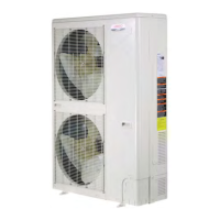
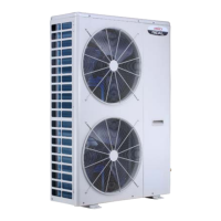
Describes the design of Value 10 condensing units for expansion valve (TXV) and RFC systems.

Shipping and Packing List

Lists the items included with the assembled 10ACB condensing unit and instructions for checking shipping damage.

General Information and Safety

General installation guidelines, code compliance, and safety notes on refrigerant venting under the Clean Air Act.

Warning: Fiberglass Wool Exposure

Warns about exposure to fiberglass wool during installation, maintenance, or repair, and potential health risks.

10 ACB Unit Dimensions

Unit Dimensions Diagrams and Table

Provides diagrams and a table listing the dimensions for various 10ACB unit models in inches and millimeters.

Setting the Unit

Installation Clearances and Mounting

Details required clearances for unit installation, slab mounting, and roof mounting, with diagrams.

Electrical Requirements and Grounding

Covers electrical wiring codes, grounding, line voltage, 24V circuits, and provides a field wiring diagram.

Plumbing

Refrigerant Piping and Connections

Instructions for refrigerant piping, line set selection, sweat connection procedures, and line kit details.

Refrigerant Metering Devices (RFCIV)

Information on RFCIV devices, drill sizes, and installation diagram for 10ACB units.

Expansion Valve Systems

RFCIV Removal and Manifold Gauge Set

Highlights the importance of RFCIV removal for expansion valves and specifies 'low loss' manifold gauge set use.

Service Valves Operation

Details on accessing service ports, opening/closing liquid/suction line valves, and their functions.

Danger: Backseating Valve Stem

Critical danger warning against backseating valve stems, which can cause component failure and injury.

Leak Testing

Warning: Pressurization Gases

Strong warning against using oxygen for pressurization; emphasizes safe use of nitrogen or CO2.

Leak Detection Methods

Outlines procedures for leak testing using HCFC-22 and nitrogen, including pressure management.

Service Valve Types

Describes suction line service valves, including ball-type for 5-ton units, and provides operational diagrams.

Evacuating

Importance of Evacuation

Explains the critical need to remove non-condensables and water vapor to prevent system corrosion and details initial evacuation steps.

Evacuation Procedure and Vacuum Levels

Covers the full evacuation process, achieving target vacuum levels, and breaking vacuum with nitrogen.

Caution: Deep Vacuum Operation

Warns against deep vacuum operation with compressors, which can cause internal arcing and damage.

Start-Up

Important: Crankcase Heater

Emphasizes energizing the crankcase heater 24 hours before start-up to prevent compressor slugging damage.

Start-Up Checklist and Charging Considerations

Provides a checklist for unit start-up and discusses initial charging considerations based on ambient temperature.

Table 3: Refrigerant Charge Adjustment

Table detailing adjustments to refrigerant charge based on line set diameter and length deviations from standard.

Table 4: Normal Operating Pressures

Table 4 Explanation and Charging Preparation

Explains Table 4 as a maintenance guide and details preparation steps for unit charging procedures.

Charging for RFC Systems

Describes weighing-in and subcooling methods for charging RFC systems based on outdoor ambient temperature.

Charging for TXV Systems

TXV Charging Methods

Details the weighing-in method (low ambient) and the approach method (high ambient) for charging TXV systems.

System Operation and Components

Covers system operation, crankcase heaters, compressor start kits, timed-off controls, and pressure switches.

Subcooling and Approach Tables

Presents tables for subcooling values for RFC systems and approach temperature targets for TXV systems.

Maintenance

Warning: Electrical Safety

Critical warning to turn off electrical power before performing any service or maintenance to avoid shock hazards.

Seasonal and Coil Maintenance

Covers essential maintenance tasks at the start of the cooling season, including condenser coil cleaning and inspection.

Indoor Unit and Component Checks

Details indoor unit maintenance like filter cleaning, blower adjustments, and checks for refrigerant sight glass installation.

Start-Up and Performance Check List

Job and Unit Information

Fields for recording essential job details, unit model, serial number, and nameplate specifications.

Cooling Section Performance Verification

Checklist items to verify proper cooling section operation, including leak checks, valve status, and refrigerant charge.

Thermostat Checks

Items to verify regarding thermostat settings, proper operation, and levelness for correct system control.

Overview

This manual describes the Lennox Value™ Series 10ACB Condensing Units, designed for residential and light commercial air conditioning applications. These units are available in capacities ranging from 1-1/2 to 5 tons. They are compatible with both expansion valve (TXV) and RFC (Refrigerant Flow Control) systems, offering flexibility in system design and application. The manual provides comprehensive instructions for installation, operation, and maintenance, ensuring proper functioning and longevity of the equipment.

Function Description

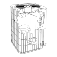
The 10ACB Condensing Unit is the outdoor component of a split-system air conditioning system. Its primary function is to reject heat from the refrigerant, which has absorbed heat from the indoor space. The unit consists of a compressor, an outdoor coil (condenser), and a fan. The compressor circulates refrigerant through the system, compressing it to a high-pressure, high-temperature gas. This gas then flows through the outdoor coil, where the fan draws ambient air over the coil fins, allowing heat to dissipate from the refrigerant to the outside air. As the refrigerant cools, it condenses into a high-pressure liquid, which then flows to the indoor evaporator coil to absorb heat from the indoor air. The system cycles on demand from a room thermostat, with the indoor blower operating continuously if the thermostat blower switch is set to "ON."

Important Technical Specifications

  • Capacities: 1-1/2 through 5 tons.
  • Refrigerant: HCFC-22. The Clean Air Act of 1990 bans intentional venting of refrigerants (CFCs and HCFCs) as of July 1, 1992, requiring approved recovery, recycling, or reclaiming methods.
  • Electrical:
    • Units are approved for use with copper conductors only.
    • 24V, Class II Circuit for low voltage connections.
    • Voltage supply must be within the range listed on the unit nameplate.
    • Minimum circuit ampacity and maximum overcurrent protection size are specified on the unit rating plate.
  • Refrigerant Metering Device: Compatible with both RFCIV (Refrigerant Flow Control IV) and TXV (Thermal Expansion Valve) systems. RFCIV bullets are shipped with the outdoor unit, and specific drill sizes are provided for various 10ACB models (e.g., 0.047 for 10ACB12, 0.092 for 10ACB60). Expansion valve kits must be ordered separately.
  • Line Set Diameters:
    • Liquid Line: 5/16 in. (8mm) or 3/8 in. (10mm) depending on unit size.
    • Suction Line: 5/8 in. (16mm), 3/4 in. (19mm), 7/8 in. (22mm), or 1-1/8 in. (29mm) depending on unit size.
    • Line length should be no greater than 50 feet (15.2 m) to ensure oil return to the compressor.
  • Refrigerant Charge Adjustment:
    • For 5/16 in. (8mm) liquid line: 2 ounces per 5 ft. (57ml per 1.5m) adjustment from 20 ft. (6.1m) line set.
    • For 3/8 in. (10mm) liquid line: 3 ounces per 5 ft. (85ml per 1.5m) adjustment from 20 ft. (6.1m) line set.
  • Crankcase Heater: Used on 3-1/2, 4, and 5-ton units. Should be energized 24 hours before start-up to prevent compressor damage.
  • Compressor Start Kit: 3-1/2, 4, and 5-ton single-phase units have internal start components and do not require field installation of a separate start kit.
  • Timed-Off Control (Option Units ONLY): Delays compressor start-up for five minutes on thermostat demand to equalize system pressures and prevent short-cycling.
  • High and Low Pressure Switches (International and Option Units ONLY):
    • High pressure switch: Manually reset, protects against high pressure conditions (e.g., fan failure).
    • Low pressure switch (SPST, NO): Automatically resets, protects against loss of charge. Trips at 15 +/- 5 psig (103 +/- 34 kPa) and resets at 25 +/- 3 psig (172 +/- 21 kPa).
  • Refrigerant Sight Glass (Option Units ONLY): Provided in the bag assembly for field installation to monitor system charge.
  • Construction: Product contains fiberglass wool insulation.

Usage Features

  • Installation Clearances: Requires a minimum of 36 inches (914 mm) clearance on one side and 12 inches on two sides, with 48 inches clearance on top.
  • Slab Mounting: Install on a level slab high enough to allow adequate water drainage.
  • Roof Mounting: Install a minimum of 4 inches above the roof surface, ensuring weight is properly distributed over roof joists and rafters.
  • Sweat Connection Procedure: Detailed steps for brazing refrigerant lines, including wrapping valve bodies with wet cloths to prevent heat damage.
  • Service Valves:
    • Liquid line and suction line service valves (sweat connections) are accessible from outside the unit.
    • Equipped with a schrader valve for leak testing, evacuation, charging, and checking charge.
    • 5-ton units (10ACB60/62) use a ball-type full service valve on the suction line.
    • Instructions for accessing the schrader port, opening, and closing service valves are provided.
  • Leak Testing: Requires pressurizing the system with a trace amount of HCFC-22 (max 2-3 pounds) and nitrogen (150 psig), then checking for leaks with an electronic leak detector or halide torch.
  • Evacuation: Critical for proper operation. System must be evacuated to an absolute pressure of 23mm of mercury (approx. 1 inch of mercury) or 0.5mm of mercury (500 microns) within a 20-minute period after shutting off the vacuum pump. Deep vacuum operation (using compressors to evacuate) is warned against as it can cause internal arcing and compressor failure.
  • Charging Procedures:
    • Weighing in the Charge: Most accurate method, especially when the system is void of refrigerant or for RFC systems with outdoor ambient below 65°F (18°C), or TXV systems below 60°F (16°C).
    • Subcooling Method (RFC Systems ≥ 65°F (18°C) Outdoor Temp): Involves measuring liquid line temperature and pressure, determining saturation temperature, and comparing subcooling to specified values in Table 5.
    • Approach Method (TXV Systems ≥ 60°F (16°C) Outdoor Temp): Involves subtracting outdoor ambient temperature from liquid line temperature and comparing the result to specified values in Table 6.
  • Normal Operating Pressures: Table 4 provides typical liquid and suction pressures (PSIG) for various models and outdoor coil entering air temperatures, serving as a general guide for maintenance checks.

Maintenance Features

  • Pre-Start-up Checks: Rotate fan to check for binding, inspect wiring for loose connections, check voltage supply, and energize crankcase heater (if applicable) 24 hours prior to start-up.
  • Seasonal Checks (Beginning of Cooling Season):
    • Clean and inspect condenser coil (flush with water hose, power off).
    • Visually inspect connecting lines and coils for oil leaks.
    • Check wiring for loose connections.
    • Check for correct voltage at unit (while operating).
    • Check condenser fan motor amp-draw.
    • If insufficient cooling is reported, gauge and check refrigerant charge.
  • Evaporator Coil Maintenance:
    • Clean coil if necessary.
    • Check connecting lines and coils for oil leaks.
    • Check and clean condensate line.
  • Indoor Unit Maintenance:
    • Clean or change filters.
    • Adjust blower speed for cooling based on pressure drop over the coil.
    • For belt drive blowers, check belt for wear and proper tension.
    • Check wiring for loose connections.
    • Check for correct voltage at unit (while operating).
    • Check blower motor amp-draw.
  • Safety Warnings:
    • Electric Shock Hazard: Turn off electrical power at disconnect switch(es) before any service or maintenance.
    • Fiberglass Wool Warning: Disturbing insulation may expose users to fiberglass wool, which can cause lung cancer, respiratory, skin, and eye irritation. Consult material safety data sheets for more information.
    • Refrigerant Venting: Prohibited by the Clean Air Act of 1990.
    • Backseating Valves: Do not attempt to backseat service valves, as this can cause the snap ring to explode under pressure.
    • Oxygen for Pressurization: Never use oxygen to pressurize refrigeration systems; it can explode on contact with oil. Use nitrogen or CO2 with a regulator set to 1 or 2 psig.
    • Deep Vacuum Operation: Avoid using compressors to evacuate the system, as extremely low vacuums can cause internal arcing and compressor failure, voiding the warranty.

Lennox Value Series Specifications

General IconGeneral
BrandLennox
ModelValue Series
CategoryHeat Pump
LanguageEnglish

Related product manuals