Do you have a question about the Lennox REAL VPC H4-3P Series and is the answer not in the manual?
| Category | Heat Pump |
|---|---|
| Series | H4-3P Series |
| Heating Capacity | 18, 000 - 60, 000 BTU/h |
| Cooling Capacity | 18, 000 - 60, 000 BTU/h |
| SEER Rating | Up to 20 |
| HSPF Rating | Up to 10 |
| Refrigerant | R-410A |
| Voltage | 208/230V |
| Phase | 3 |
| Sound Level | As low as 53 dBA |
| Dimensions | Varies by model. See manufacturer specifications. |
| Weight | Varies by model. See manufacturer specifications. |
Critical safety warnings regarding improper installation, leading to damage, injury, or death.
Cautions regarding operating VRF systems during construction to prevent unit damage.
Notes the ban on intentional venting of refrigerants and required approved methods.
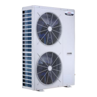
Describes the heat pump units and their use in VRF systems with R-410A refrigerant.
Details the items included in Package 1 for shipping and unpacking.
Warnings about electrical shock, fire, or explosion hazards when handling the unit.
Explains how to interpret the various components of the unit's model number.
Discusses VRF system piping requirements and the importance of the LVSS piping report.
Provides dimensional data, including corner weights and center of gravity for the unit.
Illustrates the top view of the unit with key dimensions.
Shows the front view of the unit with primary dimensions.
Provides dimensional data, including corner weights and center of gravity for the unit.
Illustrates the top view of the unit with key dimensions.
Shows the front view of the unit with primary dimensions.
Details minimum installation clearances required for a single outdoor unit.
Specifies clearances for installing multiple units placed side by side.
Outlines clearances for parallel installations in back-to-back and front-to-back arrangements.
Warnings about unit support stability and safe disposal of packing materials.
Guidelines for positioning the outdoor unit, considering sound, windows, and interference.
Important notes regarding exhaust vents and precautions for roof mounting.
Instructions on how to safely lift the unit without causing damage.
Describes methods for securing the outdoor unit to a slab or frame using anchor bolts.
Details how to secure the unit to field-provided wall-mounted brackets.
Explains the function of condensate drain holes and how to protect them.
Cautions for operating the heat pump in low outdoor ambient temperatures.
Guidelines for protecting the unit from snow and ice build-up and managing defrost water.
Instructions on constructing and installing wind barriers to protect the unit from prevailing winds.
Examples of unit placement in alcoves or enclosures with clearance requirements.
Details requirements for insulating refrigerant lines and using sealed conduit for buried pipes.
Provides guidelines for installing the outdoor unit indoors, including clearances and ductwork.
Details critical clearances for indoor installation and service access.
Outlines requirements for louver angle, makeup air, and discharge opening clearances.
Specifies requirements for ducted discharge, including inspection doors and clearance.
Provides detailed dimensions of the unit's front profile.
Safety warnings and procedures in case of a refrigerant leak.
Describes refrigerant piping and wiring connections for single and dual fan units.
Table showing the maximum number of indoor units connectable to each outdoor unit model.
Details the sizes of liquid and gas refrigerant lines for various outdoor unit models.
Explains the use of header kits and branch pipes for connecting multiple indoor units.
Specifies required straight pipe lengths before and after header kits for proper operation.
Important notes on refrigerant oil types and proper torque for flare nut connections.
Provides torque recommendations for tightening flare nuts to ensure leak-free joints.
Instructions on insulating flared connections to prevent condensation.
Details maximum permitted pipe lengths and height differences when using branch pipes.
Specifies maximum permitted pipe lengths and height differences with one header pipe kit.
Outlines maximum permitted pipe lengths and height differences with two header pipe kits.
Details maximum permitted pipe lengths and height differences with three header pipe kits.
Specifies maximum pipe lengths and height differences for non-VRF air handler/furnace connections.
Table listing main outdoor unit pipe sizes for VRF indoor units and AHU control kits.
Details main outdoor unit piping sizes for one-to-one connections to non-VRF air handlers.
Specifies allowable line set diameters for existing systems with non-VRF air handlers.
Provides main indoor piping sizes for VRF indoor units and AHU control kits.
Lists indoor piping sizes for various VRF indoor unit types.
Details total piping length and combination ratios for VRF indoor units and AHU control kits.
Best practices for brazing refrigerant piping, including nitrogen purging.
Specifications for performing pressure tests on the refrigerant system.
Step-by-step procedure for evacuating the refrigerant system using a micron gauge.
Instructions for calculating additional refrigerant charge based on liquid line pipe size and length.
Specifies additional charge per liquid line branch pipe.
Table detailing additional charge amounts based on indoor unit type and capacity.
Lists the maximum refrigerant charge amounts for different outdoor unit models.
Warnings regarding electrical safety, power supply, and circuit protection.
Cautions about proper grounding, interference avoidance, and separate power supplies.
Diagram showing power and communication terminal strip layouts on the unit.
Explains the various symbols and components used in the typical unit wiring diagram.
Illustrates typical power wiring for VRF systems, including outdoor and indoor units.
Shows communication wiring for VRF units and AHU kits, including terminating resistor.
Diagram illustrating typical communication wiring for VRF systems with header pipe kits.
Shows typical communication wiring for VRF systems using multiple header pipe kits.
Illustrates communication wiring for non-VRF air handlers with a 3H/2C thermostat.
Shows communication wiring for non-VRF air handlers with a 4H/2C thermostat.
Illustrates communication wiring for non-VRF air handlers with a 3H/1C thermostat.
Shows communication wiring for non-VRF air handlers with a 2H/2C thermostat.
Illustrates communication wiring for non-VRF air handlers with a 1H/1C thermostat.
Shows communication wiring for non-VRF air handlers with a 2H/1C thermostat.
Provides electrical parameters, including voltage, current, and motor data, for various unit models.
Explains the purpose of the magnet ring for strengthening communication cable signals.
A checklist of essential tasks to perform before starting the commissioning process.
Instructions for powering on all indoor units and the outdoor unit.
Describes how to enter the commissioning mode using the unit's buttons.
Guides on setting the type of indoor units connected to the system.
Instructions for setting the total number of indoor units in the system.
Flowchart detailing how to set the indoor unit type within the commissioning menu.
Flowchart explaining how to set the number of indoor units connected to the system.
Describes the auto-addressing and initialization phases of the commissioning process.
Explains the final status displays indicating successful commissioning or error codes.
Lists various system parameters and their corresponding values for diagnostic checks.
Details parameters related to heat exchanger status and special operating modes.
Provides parameters for sensor temperatures, voltages, and indoor unit capacities.
A comprehensive list of digital display error codes and their definitions for troubleshooting.
Explains the output displayed on DSP1 and DSP2 in various operating states.
Details the functions of the SW1 to SW4 buttons for menu navigation and selection.
Instructions on how to enter and navigate the menu mode using the unit's buttons.
Cautionary advice on using non-metallic tools when adjusting settings on the control board.
Lists functions related to error history, unit address, and refrigerant recovery.
Details functions for VIP indoor unit settings, priority modes, and unit display units.
Specifies functions related to level distance settings between indoor and outdoor units.
Includes functions for network address, indoor unit count, and communication types.
Lists target temperature settings for T2B and T2 sensors.
Contains settings for compressor lockout temperatures.
Details options for forced defrost, oil return, and emergency stop release.
Cautions regarding the conditions that must be met for safe and effective auto charging.
Step-by-step instructions and flowchart for performing the auto charge procedure.
Identifies the auto-charge port on the single fan cabinet unit.
Identifies the auto-charge port on the dual fan cabinet unit.
Provides contact details for technical support, including phone, email, and website.
Information on downloading the Lennox VRF & Mini-Splits App for technical literature.