27
Wiring Connections
1. Select the appropriate electrical inlet into the
outdoor unit. Local and national codes apply.
2. Locate the terminal strip in the outdoor unit
control box. Connect the power wiring (sized per
NEC/CEC and local codes) and communications
cable. Refer to unit nameplate for rated voltage.
In the U.S.A., wiring must conform with current local
codes and the current National Electric Code (NEC).
In Canada, wiring must conform with current local
codes and the current Canadian Electrical Code
(CEC).
Refer to unit nameplate for minimum circuit ampacity
and maximum over current protection size.
NOTE - Two-conductor, stranded, shielded cable
must be used for the communication wiring. This is
necessary to ensure proper system communication
and operation.
NOTE - The outdoor unit requires a separate circuit
breaker and power supply.
IMPORTANT
Power wiring must comply with National, State, and Lo-
cal codes.
WARNING
Isolate the power supply before accessing unit electrical
terminals.
Install unit so that unit disconnect is accessible.
Follow all local and national codes, as well as this
installation instruction, during installation. Do NOT
overload electrical circuit, as this may lead to failure
and possible re.
Use specied wiring and cable to make electrical
connections. Clamp cables securely and make sure
that connections are tight to avoid strain on wiring.
Insecure wiring connections may result in equipment
failure and risk of re.
Wiring must be installed so that all cover plates can be
securely closed.
Do not attempt to repair a damaged power cord.
Do not modify the power cord in any way. Do not
attempt to extend the length of the power cord or use
an extension cord with this appliance. Do not share the
single power outlet with any other appliances.
CAUTION
This unit must be properly grounded and protected by a
circuit breaker. The ground wire for the unit must not be
connected to a gas or water pipe, a lightning conductor
or a telephone ground wire.
Do not connect power wires to the outdoor unit until
all other wiring and piping connections have been
completed.
Install all wiring at least 3 feet away from televisions,
radios or other electronic devices in order to avoid the
possibility of interference with the unit operation.
Do not install the unit near a lighting appliance that
includes a ballast. The ballast may aect remote control
operation.
Separate power wiring supplies must be provided for
the outdoor unit and indoor unit(s).
Do not cross-connect refrigerant piping or signal wires
between VRF systems. Each VRF system must be
piped and wired separately.
Each indoor unit must have its own electrical disconnect.
Do not run signal wire and power wire in the same
conduit; keep distance between the two conduits per
local codes. (Make sure to set address of outdoor unit
in case of parallel multi-outdoor units.
Take care when making nal power and control cable
connections. Cross connection will result in damage
to unit’s main board.
Only apply power to the system after performing all
of the pre-commissioning steps.
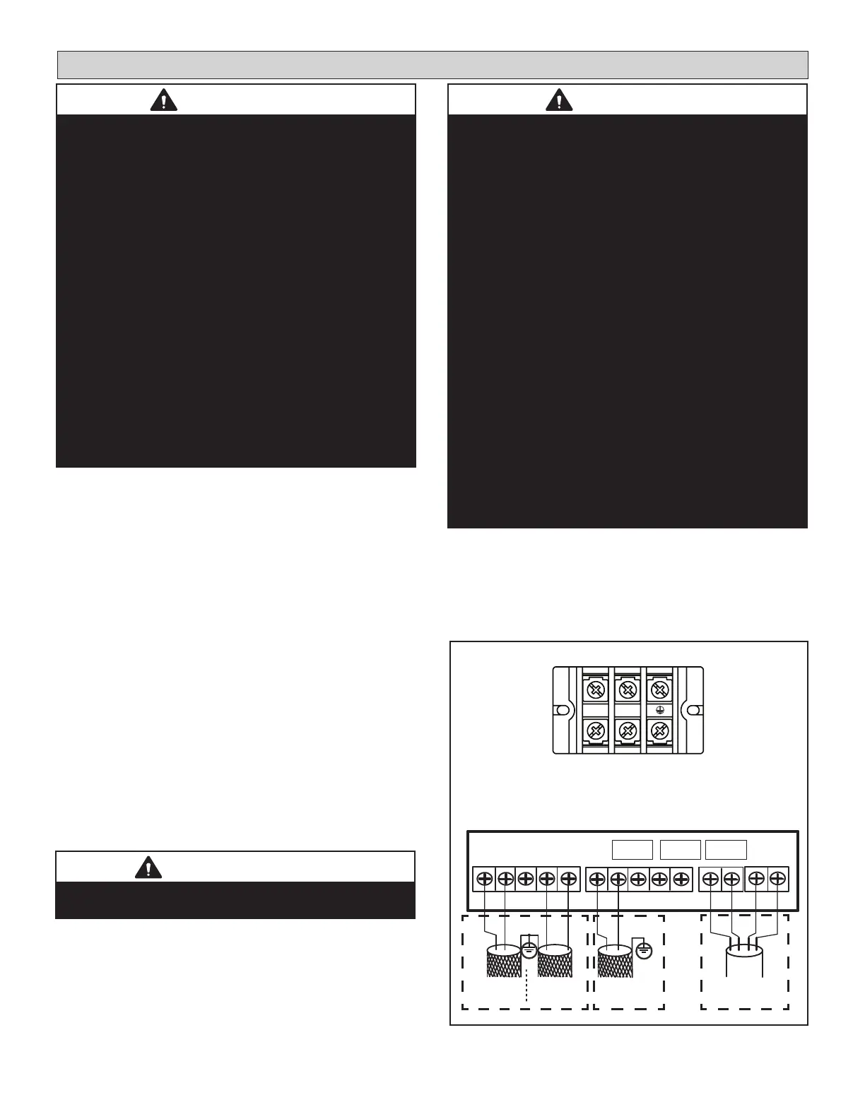
Figure 23. Wiring Terminals
NOTE - Use 18 GA 2-Conductor, Stranded, Shielded
Communication Cable for connection to VRF indoor
units. Use solid core thermostat wire for connection
to air handler or furnace.
208/230V 60Hz 1Ph
Power Supply
L1 L2
Power Terminal Strip
Communication Terminal Strip
Pulse Meter
IDU Comm.
(For VRF)
X Y E W
Controller
CN1 CN3 CN2
O
A P Q E
M1
M2 C O/B Y
AHU Comm.
(For AHU)
NOTE - Connect to either PQ terminals or CBYW
terminals but not both.
 Loading...